Welcome to the Noraxon FAQs. Use the sections below to find quick, plain‑language answers to common questions about the myoRESEARCH (MR) platform, licensing, setup, integrations, hardware connections, and data workflows across a range of applications. This page is designed to be a comprehensive yet streamlined starting point so you can address common questions and issues faster. Need more depth? Visit the Knowledge Base or contact support and we’ll help you out.

FAQs
License Activation & Deactivation
What features are available when using an academic license?
Through our Student License Program, you are given a fully unlocked, FREE 6 month license for in-depth analysis: every feature and report is available. In addition, you offered unlimited access to our technical support team. The only feature NOT available in academic licenses is data collection. Data must be collected with a full license for myoRESEARCH (MR).
To request an academic license, please fill out the Academic License Request Form. You will need an email address and the license ID associated with your system to request a license.
I need to activate a license on another computer for data collection. How do I do this?
If you've already used all allotted activations on your MR license, deactivate your license ID from the Software Setup on a computer no longer being used for data collection. This will automatically free up an activation to be used on a different computer. Deactivation instructions are shown below.
Only need a license ID for analysis and reporting purposes? You can request a free student license at our student license request page🔗. Student licenses are unlimited for every MR license, and can be used for data collection and reporting purposes only.
Deactiave a license in MR4:
Deactivate a license in MR3:
Error: _ activations have been used out of the _ activations that were purchased; no more activations are allowed
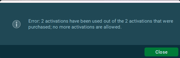
This error message means all activations available on your license ID have been used. If you need to activate MR on a new computer, it is necessary to manually deactivate your MR license on a computer you are no longer using. This will automatically free up a license to use for the new computer. Deactivation instructions are below.
Deactivate a license in MR4:
Deactivate a license in MR3:
Error: Sockets::Connection: Socket closed
The error message "Socket:: Connection: socket closed," typically indicates that the local MR software installation is unable to establish a connection with our server effectively. This could be due to various reasons, including network issues or other firewall problems.
Sometimes, allowing the MR program through the computer's firewall may solve this. If activation by internet is not possible, contact support@noraxon.com with the activation ID and version of MR you are trying to activate, and a Noraxon Support representative will send a manual activation code.

How do I deactivate my MR license to free up an activation for another computer?
Deactivating a license ID for data collection purposes will automatically free up an activation allowance to be used on another computer.
NOTE: Deactivating student license IDs is not possible as they are temporary and can only be used once. However, a new student license ID can always be requested for the purposes of data collection. Request a new student license ID here🔗.
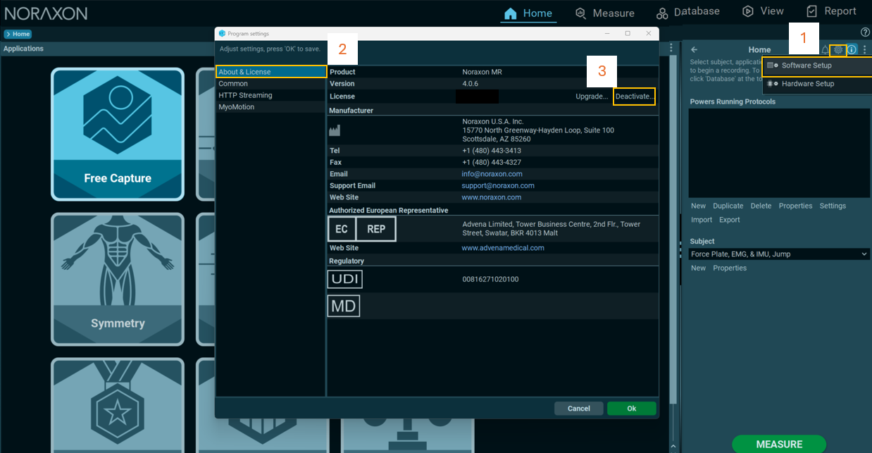
To deacitvate your license in MR4, follow the instructions below:
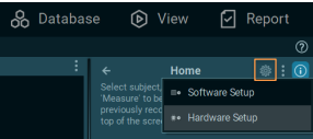
- On the Home tab, click the gear button and select Software Setup.
- Go to the About & License tab.
- Click Deactivate.
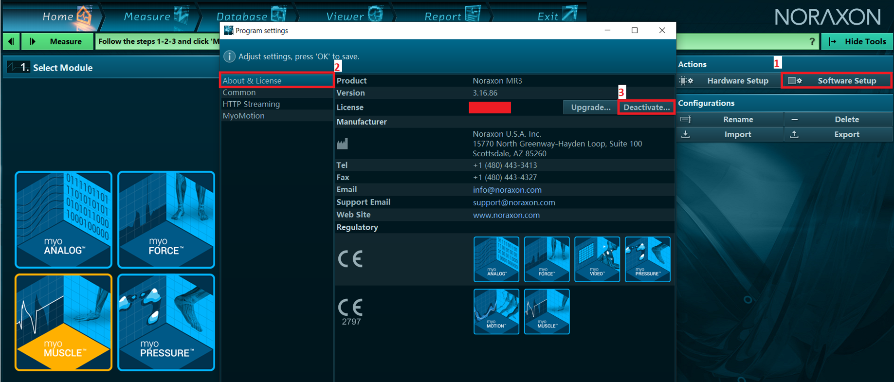
To deacitvate your license in MR3, follow the instructions below:
- On the Home tab, select Software Setup.
- Go to the About & License tab.
- Click Deactivate.
Error: This version is not included in your subscription

This message indicates you are trying to activate a version of MR that you do not have access to based on your software maintenance expiration date.
To check which version of MR you can activate with your licence, use the MR Software Maintenance Check Tool🔗. This tool will also tell you what needs to be purchased to upgrade, if desired.
To get a quote to renew your software maintenance and access the latest version of MR, contact sales@noraxon.com
To find legacy downloads for older MR versions, visit the legacy downloads page🔗.
To find the latest version of MR, visit the software downloads page🔗.
How do I update my MR software to the most current version?
The latest version of the MR software is always available for download on our Software Download page, linked below.
Installing updates to existing versions of MR requires a different process than an initial installation vs a new version.
To upgrade an existing MR installation to a newer patch of the same version (e.g. MR 4.0.90 to MR 4.0.106, reference our instructions of installing a patch update for full details🔗.
To upgrade an older version of MR (MR3 or MR 4.0) to the latest version (MR 4.2), refer to the following resources:
You may want to check whether you are eligible to upgrade to the latest MR version. To do this, check your license on our Software Maintenance Check page🔗. If you don't have access to the latest upgrade and would like to renew your software maintenance or learn more about how new features released may support your applications, Contact a Noraxon representative.
If you would like to update to the latest version of MR you have access to via your software license, visit our Legacy Software Downloads page🔗.
![]()
General System Requirements & Computer Troubleshooting
Why did MR crash while recording and/or fail to save my recording?
This often occurs as a result of the disk space on the computer being exceeded. Check that the storage drive that MR saves to has not run out of memory. Note: the crash can be accompanied by a message stating: “Error: write to file."
To check your disk space, open your File Explorer in Windows, then go to This PC. The remaining space will be listed for all available drives like below.
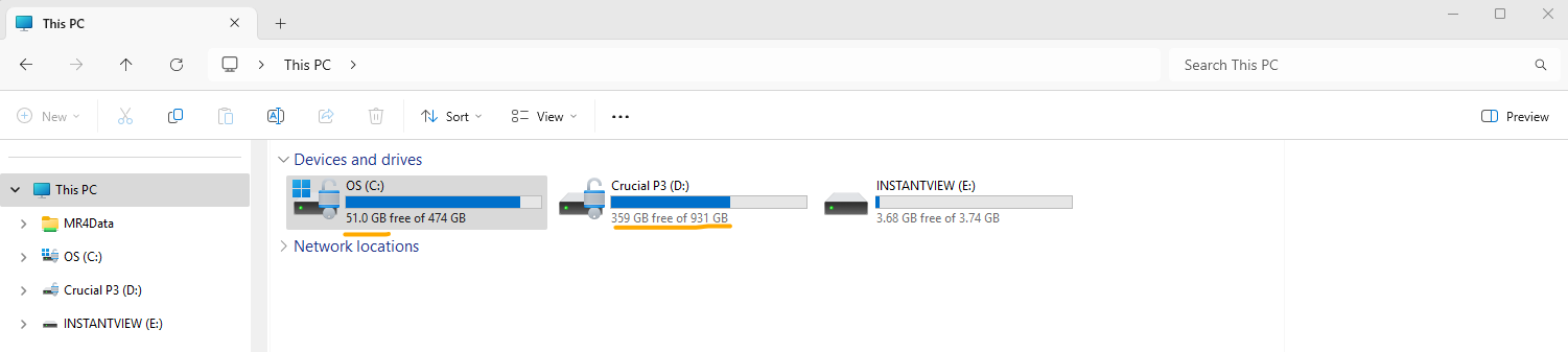
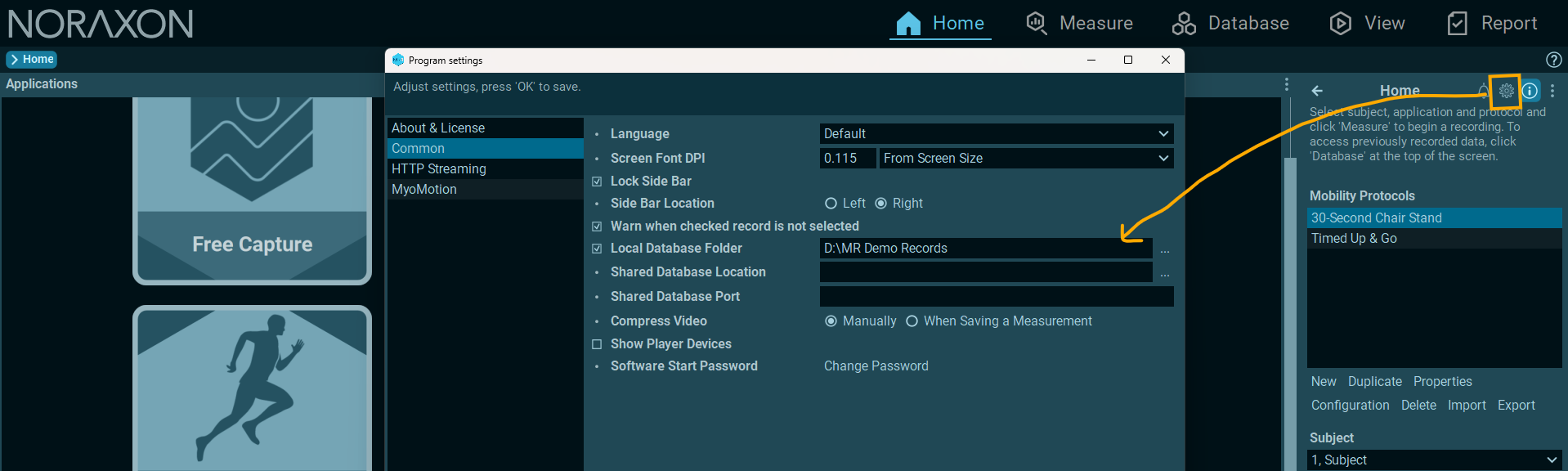
Note that MR data is automatically stored to the C drive during measurement, and during saving as long as an external local database has not been selected. To check whether you are using an external local database, you can check your software in the Software Setup > Common tab. If the "Local Database Folder" is checked with a location entered, your data is being saved to an alternative location aside from the default location on the C drive. It is recommended to check the disk space for your saving location, and clear it if limited space is available.
For more information on how to reduce file sizes by video recompression and how to back up your database to an alternate location, visit the data backup & management guide for your software version linked below.
🔗MR4 Data Backup, Management & Sharing
While the issue is likely due to disk space, it is recommended to reach out to the Noraxon Support team to narrow down the problem if the disk space looks open.
When starting MR, I received an error saying “Unable to create OpenGL 4.5 context.” What does this mean?
If it is an OpenGL error, then the issue is related to the computer's graphics card.
Either the graphics card does not meet our required minimum computer specifications🔗 or the graphics card needs to be updated. Usually, it is a matter of a simple graphics card update if your existing graphcis card meets our required minimum specifications. The video linked below shows how to update the power settings on your PC. If you have an NVIDIA graphics card, follow the same steps in the video to access the NVIDIA control panel.
Optimization of Computer Power and Graphic Settings [VIDEO]🔗
We also recommend updating to the latest drivers for the graphics card. Usually it is best to download them directly from the manufacturer (not from within Windows, as Windows can tend to be behind on the latest drivers available). You can search for the drivers for your computer's specific graphics card at the link below.
https://www.nvidia.com/en-us/drivers/
I am running into a wglCreateContextAttribsARB when I try to open the MR software. How do I solve this?
The error message referencing “wglCreateContextAttribsARB” is typically related to the graphics driver or GPU compatibility. Based on that, I recommend checking the GPU configuration on your PC. Please follow the steps below:
1. Confirm that the PC you're using meets our minimum specification requirements. Often, if a computer's CPU does not meet the required minimum specifications, this message will appear.
Noraxon MR Minimum Computer Specification Requirements🔗
2. Verify the installed GPU
Open Device Manager
Expand the Display adapters section
Confirm which GPU(s) are listed (e.g., NVIDIA or Intel). NOTE: Noraxon recommends having a discrete graphics card (NVIDIA, AMD, etc) in addition to the integrated graphics card (e.g. Intel) as the integrated graphics cards are often not powerful enough.

3. Ensure the dedicated GPU is being used by MR4
- Open the NVIDIA Control Panel
- Go to Manage 3D Settings > Global Settings
- Set the preferred GPU to High-performance NVIDIA processor
- You can follow this video guide🔗 for reference
4. Update the GPU drivers
- If the system uses an NVIDIA card, download the latest drivers from the NVIDIA Drivers page
- Install the appropriate driver for the GPU model and restart the PC
Once the GPU drivers are updated and MR4 is set to use the dedicated GPU, try launching the software again. If the issue persists despite updated graphics and power settings and the PC meets the specifications required to run the MR software, contact Noraxon Support.
What are the computer specifications required to run myoRESEARCH (MR)?
The computer specification requirmement for the myoRESEARCH (MR) software can be found here:
I am seeing an “OpenGL” error message. What does this mean and how do I solve it?
If it is an OpenGL error, then the issue is related to the computer's graphics card.
Either the graphics card does not meet our required minimum computer specifications🔗 or the graphics card needs to be updated. Usually, it is a matter of a simple graphics card update if your existing graphcis card meets our required minimum specifications. The article linked below shows how to update the power settings on your PC. If you have an NVIDIA graphics card, follow the same steps in the video to access the NVIDIA control panel.
Optimization of Computer Power and Graphic Settings [VIDEO]🔗
We also recommend updating to the latest drivers for the graphics card. Usually it is best to download them directly from the manufacturer (not from within Windows, as Windows can tend to be behind on the latest drivers available). You can search for the drivers for your computer's specific graphics card at the link below.
https://www.nvidia.com/en-us/drivers/
Synchronization & 3rd Party Integration
Is there anything that needs to be adjusted in hardware setup when collecting data from multiple Ultium Receivers?
Each system needs to be set-up for collection on their own RF channel. For example: If you have one Ultium system set-up to collect data on RF channel ‘1’, then you cannot set up another Ultium system to collect on this same channel. This will lead to data loss and unusable data.
To synchronize data, make sure all of your devices are connected to your MyoSync Master Station using a 3.5 mm stereo cable, and be sure to select the myoSync checkbox in the Hardware Setup in order to line up the data across systems.
If you have multiple Ultium Receivers or a Portable Lab, refer to the 🔗Portable Lab Getting Started Guide to learn how to configure multiple Ultium Receivers on different RF channels.
I have a sensor/device from another company, but don’t see it available in the MR Hardware Setup. How do I add it?
Noraxon supports integration of 3rd party products through digital (USB connection) of the following systems:
- Zebris pressure distribution platforms and treadmills
- Bertec force plates via the AM6800 amplifier or AM6500 amplifier
- AMTI force plates via the Optima amplifier or the AMTI optimized force plates
- Medilogic Pressure distrbution insoles
Noraxon supports integration of 3rd party products through analog integration of the following systems. Note that the Noraxon Analog Input System (AIS) must be used to integrate these devices:
- Kistler Force Plates
- Bertec Force Plates via the AM6501 amplifier or AM6800 amplifier
- Isokinetic dynamometers such as Humac Norm (CSMi) and Biodex
If the device you are looking for is not listed, it may still be possible to integrate it via analog outputs through the Noraxon Analog Input System. Consult Noraxon Support for further assistance and advice. In these cases, analog output scaling values given by the manufacturer of the product are needed.
If synchronization is needed between Noraxon and a 3rd party system, this can be done easily via hardware synchornization with TTL pulses. To learn more about this synchronization method, visit the article linked below.
Synchronizing Noraxon Devices with External Systems Using TTL Pulses🔗
I am seeing a “Sync not detected” error message when I finsh recording
A "sync not detected" error means that the MR software was looking for a sync trigger from that device, but didn't find one. Most of the time, this is because of one of the following reasons:
- The sync cable for that device is not connected correctly.
- There is a cable plugged into the "Sync In" port on the MyoSync, but there shouldn't be. (If the sync trigger is being generated for only Noraxon devices, nothing should be plugged into the "Sync in" port.). The "sync in" port is only used when triggering a recording with a 3rd party external system.
- The switch on the top of the MyoSync is flipped to the wrong direction. The MyoSync switch should be flipped to the right in the image below, so that it is pointed toward the signal that looks like a square wave that goes from low to high, then high to low (circled in blue, below)

For a list of the specific sync settings required for each Noraxon device and details on how to set up the MyoSync, reference the MR4 Synchronization Guide🔗.
Data Backup & Management
How do I import/exports records, configurations, and reports in MR? Also, how do I transfer these records to another computer?
Refer to the link below to import exported protocols, reports, and records exported from another installtion of MR4 onto another computer.
🔗How to Import Protocols, Demo Records, and Reports into MR4 from another installation
How do I backup my database in MR3 or MR4?
All data collected in the MR software is stored locally to the data collection PC. An external local database location can be created in a different spot through the MR Software Setup.
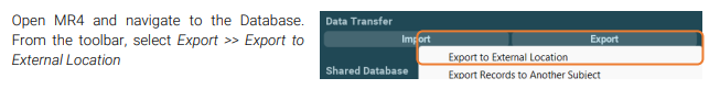
Periodically, backup the data in your database to an external location using the Export >> Export from external location operation from the Database tab.
Reference the MR4 Data Backup, Management, and Sharing Guide🔗 for full instructions on creating and maintaining a data backup.
I want to create a data backup in a location that is accessible by multiple computers. How do I do this?
The easiest way to share data among multiple PCs is to use a Shared Database location. The Shared Database can be located on a server, and allow for quick sharing and backup of data.
For more details on how to set up a Shared Database location, reference the MR4 Data Backup, Management & Sharing guide🔗.
Data can also be shared between computers by exporting MR data using the Export >> Export data to external location operation. The "Noraxon MR data" file created during this process can then be shared with others by dropping into a shared Google Drive or similar, using a flash drive, or sending over email.
I want to analyze the data I collected in MR on another computer. How can I transfer the data?
Data can be transferred between computers either by using the Shared Database (if both computers can access a shared network drive) or by manually exporting the data from the original PC and importing it onto the destination PC. This is useful for sharing data between computers in clinical settings, research, or for students sharing data in the classroom or lab.
Reference the Knowledge Base article below to learn how to export data from MR to transfer to another PC. If you want to transfer data through a Shared Database location, you can learn how to set this up in the MR Data Backup, Management, and Sharing Guide.
🔗How to Export MR data to Share with Another User or Computer
Report Generation & Customization
Does Noraxon have custom report templates available for download?
Yes! Feel free to visit our Custom Report Templates page for some custom template options. If you don't see your application here or in any default reports in MR, please contact Noraxon Support (submit a support request) for assistance. We are happy to help with report customization!
How do I customize a report for my application?
Visit our Report Generation and Customization section of our Knowledge Base for more information how report customization for various applications.
Report Customization section of Knowledge Base🔗
We are also happy to assist with custom report creation for customers with current software maintenance agreements. Reach out to Noraxon Support (submit a support request) to request report customization assistance or templates.
How do I create a report?
The report you choose is dependent on your application. For more details on running pre-built reports available in the MR software for different applications, visit the Reporting and Customization section of our Knowledge Base. Here, we have tutorials on how to run basic reports and on how to modify reports for your needs.
Report Customization Section of Knowledge Base🔗
Assistance and feedback on report customization for your specific applications and project needs is always available through Noraxon Support. Contact our support team to request a Zoom meeting to review report customization specifics for your application. (Note that this is avialable for customers with current software maintenance agreements with Noraxon).
EMG
How do I obtain a cost estimate for replacing sensor batteries that are past warranty?
You can use the cost estimate calculator available on the Battery Replacement form. Choose the sensor type for pricing.
Note: It is more expensive to replace batteries for IMU sensors as the battery replacement service also covers the cost of factory recalibration
What do the indicator lights on my sensors mean?
Ultium EMG, Core EMG, and Ultium Motion sensors:
Refer to the Ultium LED Status Guide🔗
DTS EMG/Research Pro IMU:
When in Charger (Charge Indicator – Amber):
1) Steady – Sensor is charging.
2) No LED – Battery fully charged.
When not in Charger (Status Indicator – Green):
1) Flashing quickly – The sensor is either in measurement mode or is in need of a firmware update.
2) Steady flash(Once per Second) – The sensor is in idle mode.
3) No Light – EMG must be placed in a powered charger station to be reactivated. This could be due to a depleted sensor battery or if the sensor has been deliberately placed in a special shut down mode.
4) Solid Green – There is something wrong with the sensor. Please submit a support request. To do this, hover over the ‘Support & Learn’ tab and click on the ‘Request Support” option.
How long is the battery life of my sensor?
All Noraxon sensors have Lithium Polymer batteries. These sensors are rated for a minimum of 300 charge-discharge cycles. Typical usage is 500 charge-discharge cycles. As the number of charge-discharge cycles increases the battery capacity slowly declines thereby reducing run time despite being fully charged.
Brand new batteries for Ultium EMG, Ultium Motion, DTS EMG, and Research Pro IMU sensors can operate for up to 8 hours when fully charged. If the run time of the sensors drops below 3-4 hours or to a level that is no longer suitable for the application, battery replacement should be considered. Only qualified technical personnel may perform maintenance. For battery replacement services, go to https://www.noraxon.com/battery-replacement/.
Brand new batteries for Core EMG sensors last up to 4 hours when fully charged. If the run time of the sensors drops below 1-2 hours or to a level that is no longer suitable for the application, battery replacement should be considered. Only qualified technical personnel may perform maintenance. For battery replacement services, go to https://www.noraxon.com/battery-replacement/.
NOTE: Battery replacement for Ultium EMG sensors is offered completely free of charge. A quote for battery replacement of other sensor types based on the quantity is given in the battery replacement form.
I am having issues charging my sensors, what should I do?
Issues with charging can result from a number of factors. Before filling out a support request, check the following:
1. Is the plug from the charging station to the Ultium receiver secure? Are the yellow LED's visible on the end of the charging station?
(For more information on LED statuses for sensors and chargers, refer to the Ultium LED Status & Charging Guide🔗.)
2. Is the power supply (PSU1) plugged into the back of the Ultium receiver? This power supply is what charges the sensors.
3. Is the yellow LED present on each of the Ultium sensors as they are charging? Check to ensure the sensor is facing the correct direction in the charging slot. The sensor LED should face the charging station LED.
NOTE: If the yellow LED is off on the sensor, this indicates that sensor fully charged as long as all other connections are secure. The yellow LED may turn on and off multiple times a day if the sensors are left ON (blinking blue) during a charge cycle as the charging mechanism turns on and off automatically when full charge is detected.

4. If the sensor has been charging for a long time, and the sensor cannot turn on, or the LED flashes red briefly before shutting down, this is an indication that the battery is completely dead and may need to be replaced.
To initiate a battery replacement request, fill out the link below.
I am using Noraxon EMG for my research and was wondering what the optimal window would be for smoothing data that you would recommend.
Generally it is up to the type of experiment being performed and the application. Most users typically use a window between 20-500 ms with the "RMS" smoothing operation.
For help with window selection, we recommend the following resources:
- The ABC of EMG Booklet🔗 covers general theory and insight as to the optimal window to use. The section on signal processing begins on page 27.
- The article EMG Signal Processing: Key Techniques and Practical Recommendations🔗 provides practical insight on smoothing window selection based on specific activities.
We also recommend performing a literature review of studies utilizing EMG for similar activities to cross-reference window selection.
What signal processing features are available in the MR software? How do I use them?
Refer to the resources below for details on the Signal Processing operations available in MR and how to use them.
MR Signal Processing Tools (video tutorial)🔗
EMG Signal Processing: Key Techniques and Practical Recommendations🔗
The rectification feature in Signal Processing is not working. What do I do?

How do I clean my EMG and IMU sensors?
Refer to the cleaning instructions from each hardware manual for instructions on cleaning your specific sensor.
For sanitary purposes, it is advisable to clean the back of the EMG and IMU sensors on a regular basis. Ultium sensors can be cleaned with a cloth slightly dampened with a solution of mild soap and water. Use of even mild disinfectant solutions (i.e., isopropyl alcohol swabs or household disinfectant wipes) is not recommended as they can degrade the polypropylene plastic on the sensor housing over time.
Noraxon sensors are not warranted against exposure to any of the conventional forms of sterilization (autoclave, heating, etc). Users wishing to utilize this equipment in a sterile environment, such as an operating theater, should consult Noraxon for other options.
I believe one of my Ultium sensors (Ultium EMG, Ultium Motion, or Core EMG) has a battery issue, and it may need battery replacement. How do I test this?
The best way to test would be to charge the sensors fully overnight, start a measurement with them in the morning (with the receiver plugged into power) and sensors simply sitting in the charging block (unplugged). If you notice the sensors start to die in any time frame less than 3/4 hours, (or early enough so that the runtime is no longer suitable for your application) you will know they need replacement.
I tried to recover data using the “Offline Data Recovery” option, but it didn’t work. How can I fix this?
Offline Data Recovery is recommended when data loss is extensive or intermittent for long recordings. To recover data offline ensure the system is plugged in as described below:
- Each sensor must be in the charging station, and the charging station must be connected to the Ultium receiver.
- The Ultium receiver should be connected to the computer
- Each sensor should be turned on (LEDs blinking blue)

When you're ready to recover data offline, use the Import function in MR and select the Import Offline Data Recovery option from the Database.
NOTE: If recovery fails, check the connections:
- Charging station should be plugged in securely to the Ultium receiver (press both ends in firmly)
- Sensors must be blinking blue
- Sensor LEDs should face the charging station LED (sensors not placed backwards)
- Ensure sensors make complete contact with charger pins (press down firmly)


For best results, recover data offline as soon as possible after the measurement has ended, and avoid recording more trials. Data stored to the flash memory on board each sensor is automatically over-written when more data is recorded after the memory is full. Each sensor can store up to 8 hours worth of data.
For more details about online and offline data recovery, reference the relevant user manual for your systme in the Lossless Data Recovery section.
I am running into issues with data loss during measurement. What can I do to fix this?
The Ultium System supports “lossless” data recovery. The sensors continue to capture and store data (>8 hours of data) when communication is temporarily lost with the receiver. Once the record is completed, the data can be recovered later in two ways:
1. Real-time (online recovery) is initiated immediately after saving a recording.
2. Later recover (offline recovery) via the Import function is available after cancelling online data recovery (choosing "Recover later")
Those two methods of data recovery are possible with all sensors in the Ultium line (Ultium EMG, Ultium Motion, and Core EMG), and are detailed below.
Online Data Recovery starts immediately after saving a measurment (using the Save & measure again or Save & View options) automatically. You know sensors are recovering data when you see the "Recovering, please wait..." message on the screen.
During this process, each sensor transmits wirelessly any packets of data that could not be transmitted in real time due to wireless interference or distance to the Ultium receiver. We recommend that the subject wearing the wireless sensors remains close to the Ultium receiver (2-5 m away) during data recovery.
Note: Online data recovery can be slow when data loss is extensive or intermittent for longer recordings. In these cases, we recommend following the process for Offline Data Recovery, as it works 20x faster than Online Data Recovery.
Offline Data Recovery is recommended when data loss is extensive or intermittent for long recordings. To recover data offline, follow the steps below:
Ensure the following connections between the sensors and the Ultium receiver:
- Each sensor must be in the charging station, and the charging station must be connected to the Ultium receiver.
- The Ultium receiver should be connected to the computer
- Each sensor should be turned on (LEDs blinking blue)
When you're ready to recover data offline, use the Import function in MR and select the Import Offline Data Recovery option from the Database.
For best results, recover data offline as soon as possible after the measurement has ended, and avoid recording more trials. Data stored to the flash memory on board each sensor is automatically over-written when more data is recorded after the memory is full. Each sensor can store up to 8 hours worth of data.
For more details about online and offline data recovery, reference the relevant user manual for your systme in the Lossless Data Recovery section.
My EMG signal is noisy. What checks can I perform to check the signal quality?
If the EMG signal or baseline is noisy, check the following:
1. Ensure good connection from the EMG sensor to the electrode.
If using Ultium EMG, ensure the lead is connected to the sensor, and the leads are properly attached to the electrode.
If using Core EMG, ensure the electrode is properly connected to the back of the Core EMG sensor.
For more information on sensor placement/adherence, reference the EMG Skin Prep, Electrode Placement, and Signal Check Tutorial🔗.
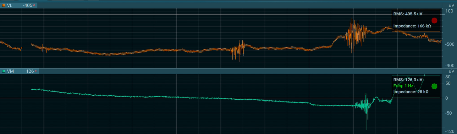
2. Make the checks listed in the Evaluating EMG Signal Quality🔗 document.
Perform the checks listed to check resting baseline noise, signal impedance, and frequency interference.
3. Swap sensors/replace the electrode.
To rule out the possibility the bad signal is related to the sensor or the electrode, swap with another sensor, or replace the electrode.
My EMG baseline is “wandering.” What causes this effect?
A "wandering baseline" effect in the EMG signal can be present when there are no high-pass filters applied to the raw signal.
This is the expected behavior of an EMG waveform with no high-pass filters applied. The drift is related to the behavior of the electrodes—There is a small DC voltage created by the two electrodes in contact with the body. It is typically on the order of millivolts, and changes to this small voltage over time will appear as a drift in the baseline of the EMG waveform. It looks pretty strange if you're unfamiliar with this phenomenon! Below is an example of what it looks like (the baseline drifts around "0".)
Normally, the high-pass filter applied as the default for Ultium sensors (e.g. 10 Hz) eliminates the low-frequency content of the signal which contains the offset caused by the voltage difference between two electrodes. With the DC offset removed, a flat baseline is achieved. Other EMG manufacturers have built-in hardware filters on their surface EMG sensors because a bandpass filter is a basic requirement for measuring surface EMG. In the case of Ultium, the "No filter" option is necessary for other kinds of (non-EMG) signals.
Note that the digital filters selectable from the Hardware Setup are not shown in the processing history. Unless it is changed, the default is a 10 Hz highpass filter and 500 Hz lowpass filter.

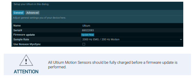
How do I update the firmware on my Ultium system?
The internal program (firmware) inside all Ultium devices can be updated via MR. After a software upgrade, the user will be notified if an update to the firmware is required with a message that appears before measurement.
To check whether there is an update available, navigate to the Hardware Setup, then open the settings for the Ultium device by double-clicking on the Ultium icon.
NOTE: There are two updates typically required. The first "Update Now" button updates the Ultium receiver firmware. After the Ultium receiver firmware is updated, a second button will appear — "Update Sensors." Both updates should be performed to update the receiver firmware and the sensor firmware.
When the firmware update is initiated, the Ultium receiver should be plugged into the computer via USB, and the sensors should be in the charging stations, connected to the receiver, and powered ON.
For more information on device setup or firmware updates after a software upgrade, review the relevant user manual for your device.
IMU (3D Motion Capture)
How do I obtain a cost estimate for replacing sensor batteries that are past warranty?
You can use the cost estimate calculator available on the Battery Replacement form. Choose the sensor type for pricing.
Note: It is more expensive to replace batteries for IMU sensors as the battery replacement service also covers the cost of factory recalibration
What do the indicator lights on my sensors mean?
Ultium EMG, Core EMG, and Ultium Motion sensors:
Refer to the Ultium LED Status Guide🔗
DTS EMG/Research Pro IMU:
When in Charger (Charge Indicator – Amber):
1) Steady – Sensor is charging.
2) No LED – Battery fully charged.
When not in Charger (Status Indicator – Green):
1) Flashing quickly – The sensor is either in measurement mode or is in need of a firmware update.
2) Steady flash(Once per Second) – The sensor is in idle mode.
3) No Light – EMG must be placed in a powered charger station to be reactivated. This could be due to a depleted sensor battery or if the sensor has been deliberately placed in a special shut down mode.
4) Solid Green – There is something wrong with the sensor. Please submit a support request. To do this, hover over the ‘Support & Learn’ tab and click on the ‘Request Support” option.
How long is the battery life of my sensor?
All Noraxon sensors have Lithium Polymer batteries. These sensors are rated for a minimum of 300 charge-discharge cycles. Typical usage is 500 charge-discharge cycles. As the number of charge-discharge cycles increases the battery capacity slowly declines thereby reducing run time despite being fully charged.
Brand new batteries for Ultium EMG, Ultium Motion, DTS EMG, and Research Pro IMU sensors can operate for up to 8 hours when fully charged. If the run time of the sensors drops below 3-4 hours or to a level that is no longer suitable for the application, battery replacement should be considered. Only qualified technical personnel may perform maintenance. For battery replacement services, go to https://www.noraxon.com/battery-replacement/.
Brand new batteries for Core EMG sensors last up to 4 hours when fully charged. If the run time of the sensors drops below 1-2 hours or to a level that is no longer suitable for the application, battery replacement should be considered. Only qualified technical personnel may perform maintenance. For battery replacement services, go to https://www.noraxon.com/battery-replacement/.
NOTE: Battery replacement for Ultium EMG sensors is offered completely free of charge. A quote for battery replacement of other sensor types based on the quantity is given in the battery replacement form.
I am having issues charging my sensors, what should I do?
Issues with charging can result from a number of factors. Before filling out a support request, check the following:
1. Is the plug from the charging station to the Ultium receiver secure? Are the yellow LED's visible on the end of the charging station?
(For more information on LED statuses for sensors and chargers, refer to the Ultium LED Status & Charging Guide🔗.)
2. Is the power supply (PSU1) plugged into the back of the Ultium receiver? This power supply is what charges the sensors.
3. Is the yellow LED present on each of the Ultium sensors as they are charging? Check to ensure the sensor is facing the correct direction in the charging slot. The sensor LED should face the charging station LED.
NOTE: If the yellow LED is off on the sensor, this indicates that sensor fully charged as long as all other connections are secure. The yellow LED may turn on and off multiple times a day if the sensors are left ON (blinking blue) during a charge cycle as the charging mechanism turns on and off automatically when full charge is detected.
4. If the sensor has been charging for a long time, and the sensor cannot turn on, or the LED flashes red briefly before shutting down, this is an indication that the battery is completely dead and may need to be replaced.
To initiate a battery replacement request, fill out the link below.
How do I clean my EMG and IMU sensors?
Refer to the cleaning instructions from each hardware manual for instructions on cleaning your specific sensor.
For sanitary purposes, it is advisable to clean the back of the EMG and IMU sensors on a regular basis. Ultium sensors can be cleaned with a cloth slightly dampened with a solution of mild soap and water. Use of even mild disinfectant solutions (i.e., isopropyl alcohol swabs or household disinfectant wipes) is not recommended as they can degrade the polypropylene plastic on the sensor housing over time.
Noraxon sensors are not warranted against exposure to any of the conventional forms of sterilization (autoclave, heating, etc). Users wishing to utilize this equipment in a sterile environment, such as an operating theater, should consult Noraxon for other options.
I believe one of my Ultium sensors (Ultium EMG, Ultium Motion, or Core EMG) has a battery issue, and it may need battery replacement. How do I test this?
The best way to test would be to charge the sensors fully overnight, start a measurement with them in the morning (with the receiver plugged into power) and sensors simply sitting in the charging block (unplugged). If you notice the sensors start to die in any time frame less than 3/4 hours, (or early enough so that the runtime is no longer suitable for your application) you will know they need replacement.
My data coming from my IMU system looks skewed. How do I troubleshoot this?
There are several factors that can contribute to the avatar looking skewed drifted, including sensor placement, calibration, and whether Returns to the Ref Pose are used to correct for drift.
Ensuring the sensors are placed correctly and the calibration is performed well are crucial steps for data integrity. Here are some initial troubleshooting steps to follow before contacting Noraxon Support for further assistance.
1. Check to ensure sensors are placed correctly on all body segments. The sensors must be oriented so that the LED is pointing upwards, and sensors placed bileterally should be symmetric on both sides. For more details about sensor placement, follow our IMU Sensors Placement Video Tutorial🔗 and sensor placement instructions in the Ultium Motion Quick Start Guide🔗.
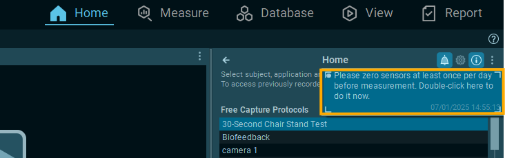
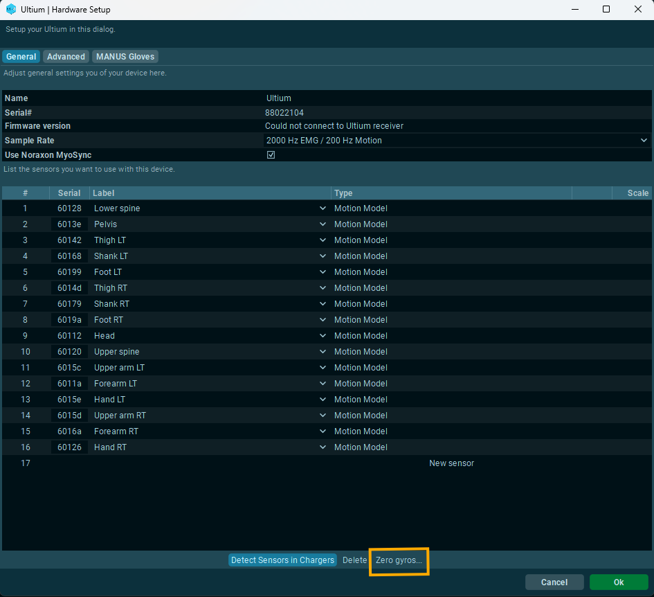
2. Zero Gyros each day before measurement. This step is meant to remove any offset bias from the internal gyro components, and is necessary as a maintenance procedure.
Gyros can be zeroed by clicking on the notifications bell from the Home tab or from the Ultium device setup in the Hardware Setup.
Zero gyros from the Home tab:
Zero Gyros from the Ultium Device Setup:
3. Ensure you are using a Functional Calibration routine (e.g. the Walking Calibration or Forward Lean Calibration) and that you are capturing Returns to Ref Poses at least at the beginning and the end of each measurment, or more often for longer recordings. The tutorials linked below contain instructions for both options.
Forward Lean Calibration Tutorial🔗
4. Ensure you are calibrating again for each subject or after moving the IMU sensors. The calibration is only good for as long as the sensors remain in the same positions they were in during the initial calibration. If the sensors are moved to a new subject or are removed and replaced on the same subject, re-calibration using the Walking or Forward Lean calibration is necessary.
If issues persist, contact Noraxon Support for further troubleshooting steps and advice.
I think I’m running into magnetic interference with my IMU system. How do I troubleshoot this?
When a functional calibration (e.g. Walking, Forward Lean, or MultiPose calibration) is used, you shouldn't experience any magnetic distortion. Those routines are designed to be magnetically immune and are not affected by environmental factors or magnetic distortion. When combined with Returns to Ref Pose during measurement, the functional calibrations can effectively eliminate all gyro drift.
For more details on recommended calibration processes, follow the video tutorials linked below.
- Walking Calibration Tutorial🔗
- Forward Lean Calibration Tutorial🔗 (perform this one if all lower body sensors are not available or when limited space is available).
If drift or distortion issues persist after performing a functional (walking or forward lean) calibration routine combined with Returns to Ref Pose, reach out to Noraxon Support for further assistance.
I tried to recover data using the “Offline Data Recovery” option, but it didn’t work. How can I fix this?
Offline Data Recovery is recommended when data loss is extensive or intermittent for long recordings. To recover data offline ensure the system is plugged in as described below:
- Each sensor must be in the charging station, and the charging station must be connected to the Ultium receiver.
- The Ultium receiver should be connected to the computer
- Each sensor should be turned on (LEDs blinking blue)
When you're ready to recover data offline, use the Import function in MR and select the Import Offline Data Recovery option from the Database.
NOTE: If recovery fails, check the connections:
- Charging station should be plugged in securely to the Ultium receiver (press both ends in firmly)
- Sensors must be blinking blue
- Sensor LEDs should face the charging station LED (sensors not placed backwards)
- Ensure sensors make complete contact with charger pins (press down firmly)
For best results, recover data offline as soon as possible after the measurement has ended, and avoid recording more trials. Data stored to the flash memory on board each sensor is automatically over-written when more data is recorded after the memory is full. Each sensor can store up to 8 hours worth of data.
For more details about online and offline data recovery, reference the relevant user manual for your systme in the Lossless Data Recovery section.
I am running into issues with data loss during measurement. What can I do to fix this?
The Ultium System supports “lossless” data recovery. The sensors continue to capture and store data (>8 hours of data) when communication is temporarily lost with the receiver. Once the record is completed, the data can be recovered later in two ways:
1. Real-time (online recovery) is initiated immediately after saving a recording.
2. Later recover (offline recovery) via the Import function is available after cancelling online data recovery (choosing "Recover later")
Those two methods of data recovery are possible with all sensors in the Ultium line (Ultium EMG, Ultium Motion, and Core EMG), and are detailed below.
Online Data Recovery starts immediately after saving a measurment (using the Save & measure again or Save & View options) automatically. You know sensors are recovering data when you see the "Recovering, please wait..." message on the screen.
During this process, each sensor transmits wirelessly any packets of data that could not be transmitted in real time due to wireless interference or distance to the Ultium receiver. We recommend that the subject wearing the wireless sensors remains close to the Ultium receiver (2-5 m away) during data recovery.
Note: Online data recovery can be slow when data loss is extensive or intermittent for longer recordings. In these cases, we recommend following the process for Offline Data Recovery, as it works 20x faster than Online Data Recovery.
Offline Data Recovery is recommended when data loss is extensive or intermittent for long recordings. To recover data offline, follow the steps below:
Ensure the following connections between the sensors and the Ultium receiver:
- Each sensor must be in the charging station, and the charging station must be connected to the Ultium receiver.
- The Ultium receiver should be connected to the computer
- Each sensor should be turned on (LEDs blinking blue)
When you're ready to recover data offline, use the Import function in MR and select the Import Offline Data Recovery option from the Database.
For best results, recover data offline as soon as possible after the measurement has ended, and avoid recording more trials. Data stored to the flash memory on board each sensor is automatically over-written when more data is recorded after the memory is full. Each sensor can store up to 8 hours worth of data.
For more details about online and offline data recovery, reference the relevant user manual for your systme in the Lossless Data Recovery section.
How do I update the firmware on my Ultium system?
The internal program (firmware) inside all Ultium devices can be updated via MR. After a software upgrade, the user will be notified if an update to the firmware is required with a message that appears before measurement.
To check whether there is an update available, navigate to the Hardware Setup, then open the settings for the Ultium device by double-clicking on the Ultium icon.
NOTE: There are two updates typically required. The first "Update Now" button updates the Ultium receiver firmware. After the Ultium receiver firmware is updated, a second button will appear — "Update Sensors." Both updates should be performed to update the receiver firmware and the sensor firmware.
When the firmware update is initiated, the Ultium receiver should be plugged into the computer via USB, and the sensors should be in the charging stations, connected to the receiver, and powered ON.
For more information on device setup or firmware updates after a software upgrade, review the relevant user manual for your device.
2D Markerless
How do I make edits to the joint angles for each parameter in the Powers Running Assessment?
For more detilas on editing and reviewing events in the Powers Running Assessment, visit the tutorial video below.
How to Review and Correct Events in the Powers Running Assessment [VIDEO]🔗
How do I interpret the results of the Powers Running Assessment?
For more details on data interpretation for the Powers Running Assessment, review the Powers Running Assessment User Guide (sections on biomechanical interpretation and investigation profiles) and our webinar with Dr. Powers as be explains how the investigation profiles available in the MR software relate to the visible parameters.
Powers Running Assessment User Guide🔗
Powers Running Assessment Addressing Lower Extremity Pathomechanics [WEBINAR]🔗
How can I compare data from the 2D markerless tracking to the Ultium Motion IMU system?
2D and 3D angles are not directly comparable. While the Ultium Motion IMU system works to measure motion based on sensors, the accuracy of the 2D markerless system is entirely dependent on the camera setup.
For more information on understand the difference between 2D and 3D data, visit our Knowledge Base article, Understanding the Limitations of 2D Video Analysis vs. 3D IMU-Based Motion Capture🔗.
When I tried tracking my measurement, the tracking failed or my report was blank. How do I fix this?
Whenever tracking fails, ensure you are following the best practices outlined in the Tips of Markerless Tracking document🔗.
Here are some initial suggestions:
- Ensure the entire subject is visible and in frame thorughout the tracking interval. If part of the subject's body is cut off, tracking will not work.
- Ensure there is only one subject in frame or that no other people are visible in the background.
- Ensure adequate contrast between the person and the background, and adequate lighting.
- Ensrure the camera is set up perpendicularly to the movement to reduce parallax error so accurate angles can be captured. For more details on the importance of camera setup as it relates to parallax error, review the Understanding the Limitations of 2D Video Analysis vs. 3D IMU-Based Motion Capture article🔗.
How do I set up my cameras for the most accurate angle tracking with the 2D Markerless system?
Visit our 2D Markerless Getting Started Guide🔗 for details on how to set up the cameras and a measurement.
For more details on camera position, environment, and subject attire for best tracking practives, refer to our Tips for Markerless Tracking Guide🔗.
Cameras
Error: “Unable to create camera device” (Ninox)
This error occurs when you attempt to access camera settings while the Ninox camera is not plugged into the computer or is not enabled via the Hardware Setup. Here are some troubleshooting steps:
1. Navigate to the Hardware Setup and ensure that the camera you are trying to record with is available in the “Selected devices” section.
- Note: If the camera is available but grayed out, try unplugging the camera and plugging it back in.
2. If the error still occurs after verifying the connection, make sure the connections on the end that goes to the PC and on the end that plugs into the camera are secure. You can also try plugging the camera into a different USB port.
- Note: Ensure the camera is plugged into a USB 3.0 port. USB 3.0 ports have "SS" printed next to the port or have blue plastic inside.
3. If you have two cameras, try swapping with a different cable to rule out the possibility of a bad cable. This can tell us whether the issue follows the camera or the cable so we can narrow down a potential hardware issue.
If you still see the same error, please contact Noraxon Support to help you narrow down the problem. Hover over the ‘Support & Learn’ tab and click on the ‘Request Support” option.
I can only see 30 and 60 FPS options and the resolution is very low on my Ninox camera
This means that the computer is registering the camera as a USB 2.0 device (instead of a USB 3.0 device). The camera is not receiving enough power from the PC to achieve higher frame rates and resolutions. Try the following steps to ensure there is enough power getting to the camera, or to identify a hardware issue:
Check USB port compatibility. Make sure the camera is plugged into a USB 3.0 port on the computer (indicated by an “SS” signal or by the color blue on the inside of the port).
Note: If a direct USB port is not available, the camera can be plugged into a USB-C hub with (1) other camera. It is not recommended to plug more than 2 cameras into a single USB-C hub as this can limit the USB bandwidth to the cameras.
Swap USB ports with a different camera. If you have more than one camera, try swapping the USB port from the working camera. This can confirm a USB bandwidth problem.
Swap cables with a different camera. If you have more than one camera and swapping the USB port didn't help, disconnect the cables from each camera and switch them. If the issue follows the camera, we know it is a camera-related issue. If the issue follows the cable, we know it is a cable-related issue and the cable may need to be replaced.
Replacement cables for Ninox 125, Ninox 250, and Ninox 300C cables can be purchased below.
If you believe you need a replacement cable and that your camera may still be under warranty, submit a support request for further assistance.
Check computer power optimization settings. If the issue persists regardless of camera, cable, or USB configuration, optimize your computer graphics card and performance settings according to the details in the article linked below.
Optimization of Computer Power and Graphic Settings [VIDEO]🔗
If the above steps do not help solve the issue, contact Noraxon Support for more assistance in narrowing down the problem. Hover over the ‘Support & Learn’ tab and click on the ‘"Request Support” option.
Force Plates
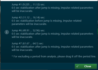
While running a Jump Analysis report, I am seeing an error message that tells me “0.5 sec stabilization after jump is missing, impulse-related parameters will be inaccurate.
Post-stabilization begins when the landing phase ends. The pre-stabilization and post-stabilization phases provide an initial condition for calculations involving impulse as well as center of mass velocity and position, which are sensitive to even slight movement.
Usually, you will see this error if the athlete performing the test does not stabilize after a jump or wait long enough between multiple jumps during a countermovement jump or squat jump test. To fix this, instruct the athlete to wait slightly longer between jumps.
What happens if I do not remove jumps related to the error message, “0.5 sec stabilization after jump is missing, impulse-related parameters will be inaccurate,” from my report?
The impulse-related calculations for that jump (e.g. jump height by net impulse, etc) will be inaccurate. The pre-stabilization and post-stabilization phases comprise the weight used in all impulse calculations for each jump, and if the stabilization phases cannot be detected, then the location of each jump phase along the timeline will not be accurate.
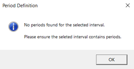
My jumps could not be defined when running a report in MR. What can I do to troubleshoot?
The error is most commonly shown if the Body Weight interval cannot be detected. The body weight calculation influences the detection of phases and calculation of impulse-based parameters.
If the Body Weight interval is not detected, check your vertical force data to see if one of the following scenarios occurred:
Scenario #1: There is no 0.5 interval of stabilization before the athlete begins jumping or after the athlete is finished jumping.
What happened?
The athlete did not stabilize long enough before or after jumping for body weight to be detected.
How to fix it:
Instruct your athlete to stand still on the force plate for at least 0.5 seconds before beginning to jump.
Additional tips: The body weight interval is calculated from the beginning of the record to the beginning of the first jump. If body weight cannot be calculated in this interval, it is calculated from the end of the last jump to the end of the record. The body weight interval is detected when the total vertical force stays within 5% within the mean for 0.5 seconds.
Scenario #2: The vertical force (Fz) time series data reads <0 N during the flight phase for the jump and 0 N when body weight should be detected.
What happened?
Someone was standing on the force plate when while the force plates were zeroed before a measurement, which occurs during the “Activating Hardware” screen before recording.
How to fix it:
Instruct your athletes to stand off the force plate while activating hardware before a measurement.
I noticed my jump type is listed at the top of the Jump Analysis report. If this is not the type of jump I collected, how do I change it?
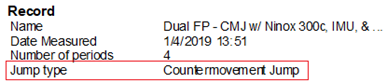
The jump type listed is the type of jump detected in MR. If this jump type does not reflect the type of jump you meant to collect, evaluate your jump workflow using the myoFORCE Jump Metrics & Definitions and Jump Analysis Video Tutorial guides as a resource.
🔗myoFORCE Jump Protocols & Metrics [PDF]
How do I remove jumps the software detected from my report?
Refer to the video from our Knowledge Base, linked below.
Treadmills
I’m seeing an “E02” error message on my h/p/cosmos treadmill. What do I do?
The E02 error message appears once a year or once every 5000 km and indicates it is time for preventative maintenance service. It doesn't mean there is anything wrong with the treadmill. You should schedule regular maintenance sometime soon, but you can disable the error code and continue using the treadmill in the meantime. You can think of it like your car showing you a service message error code to let you know it's time to get your oil changed. To reset the E02 service message from the user menu of the treadmill, reference the video below.
If you need to schedule preventative maintnenace soon, know that Noraxon doesn't offer service contracts for preventative maintenance. However, you have a few options for scheduling it moving forward.
1. You can hire any treadmill technician local to your area to perform the service. If your organization has trusted technicians for other equipment you have, they should also be able to perform the maintenance. Mainly, the running surface needs to be lubricated, the belt adjusted, the speed and incline modules checked, and the area under the motor hood visually inspected and cleaned.
2. We can hire one of our technicians through our 3rd party network to service your treadmill. If you'd like for us to send a quote and get this process started, please reach out to support@noraxon.com. We will need to know the serial number of your treadmill.
The link below contains all of the documents you or a technician will need to perform the preventative maintenance, including the maintenance checklists, user manual, and measurement forms.
https://we.tl/t-hbaxnDCIHS
Belt lubrication is detailed in the user manual (in section 11.3, and adjustment of the belt is detailed in section 11.4).