

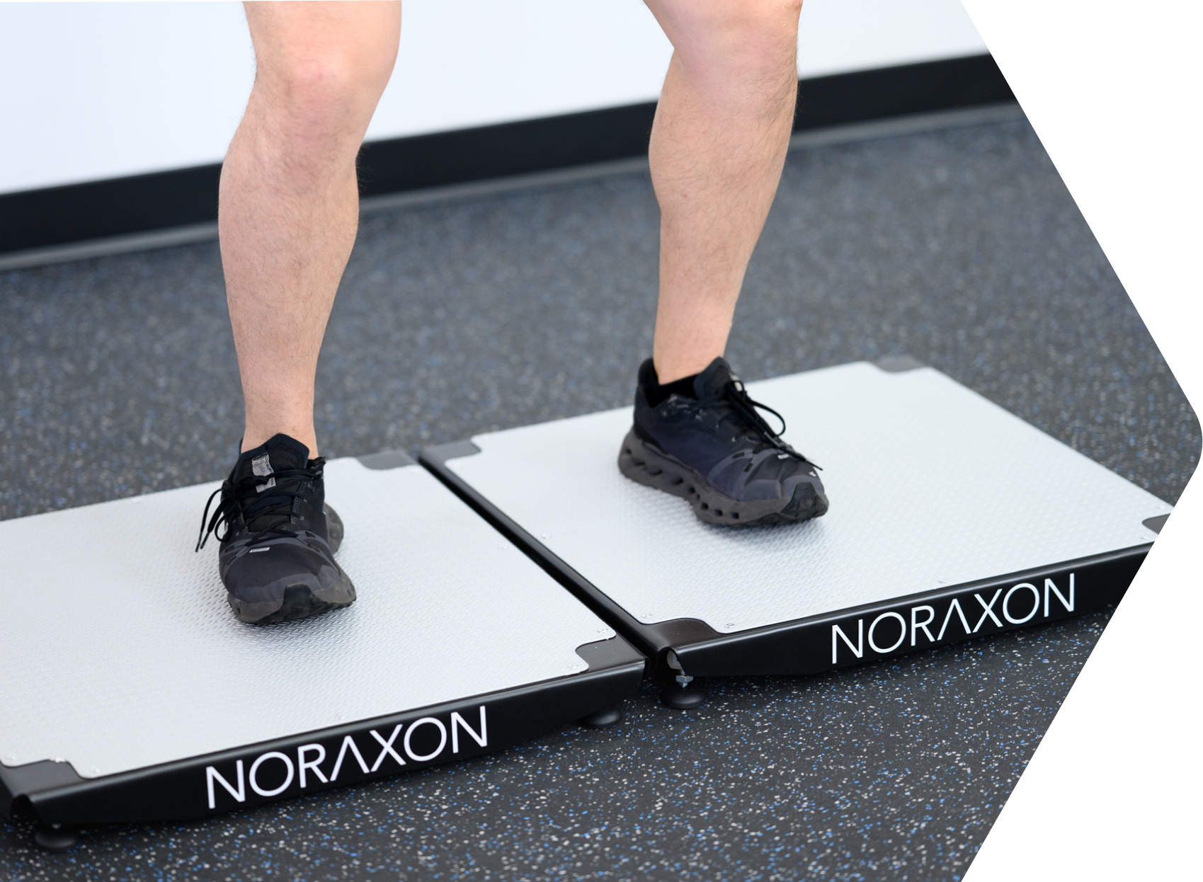
This guide will provide you with step by step instructions on how to install your new hardware and software, adjust device settings, and record your first data set.
Intended Use
Vector Force Plates provide a practical and efficient solution for measuring vertical ground reaction forces in performance testing, training, research, and applied movement analysis.
System Unboxing
Your system consists of the Vector force plate with built in data cable (USB) and sync cable (3.5 mm).
Common configurations:
- Two force plates and a myoSYNC
- Two force plates, a myoSYNC, and 1-2 NiNOX cameras
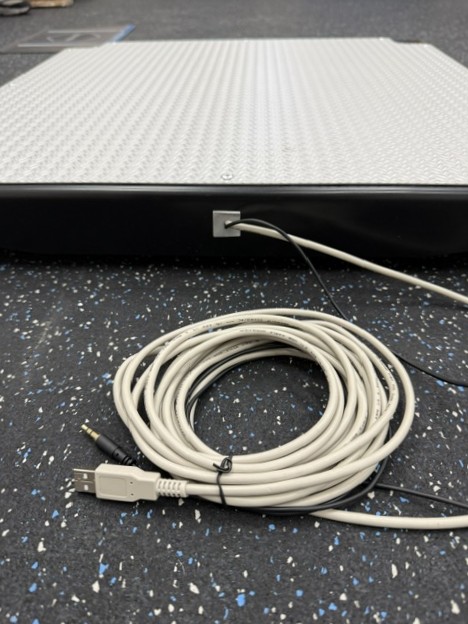
Fig 1: Vector Force Plate with data and sync cables (part #980)
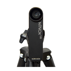
Fig 2: NiNOX 120 camera (part #144) — optional
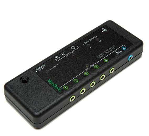
Fig 3: myoSYNC (part #262)
Installing the Companion Software – myoRESEARCH
NOTE: The Vector 1D Force Plate is only supported in software versions MR 4.2026.4 or later.
To utilize the full functionality of the Vector Force Plate system, and ensure the system has updated drivers, Noraxon’s myoRESEARCH (MR) software needs to be installed on the computer.
NOTE: The Vector Force Plates require drviers pre-installed by the MR software installation.
To download the software:
- Download the newest version of MR on our website’s 🔗Software Downloads page.
- Open the installer application (e.g. noraxon.mr.4.2026.4) and follow the instructions.
- After installation, an icon will be created on the desktop.
The video below demonstrates how to install the MR software.
Companion Software Activation
The companion software must be activated before unrestricted use is possible.
- Open myoRESEARCH.
- A dialog box will indicate how many more times MR can be opened in trial mode.
- Click Activate.
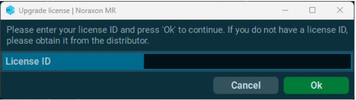
- Enter the License ID provided on your USB flash drive and click Ok.
- If you have an internet connection, click Activate by Internet for immediate activation.
- Alternatively, email the provided activation ID to activations@noraxon.com
- Noraxon Support will email the activation code within 24 hours.
- Enter the provided activation code to remove any restrictions on use.

Configuring the Hardware
Before the Vector Force Plate system can be used, the device software settings must be configured to recognize the different components that make up the system. The myoFORCE software module is required to collect force plate data in MR.
Step 1:
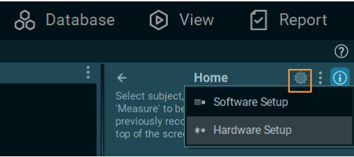
Open the MR software, click on the settings icon in the upper right-hand corner, then click Hardware Setup.
Step 2:
Select the Vector Force icon within the ‘New Device’ area, then click on the Insert button OR click and drag the New Device → Selected Devices.

NOTE: The myoSYNC (required for more than one force plate) and NiNOX camera (optional) should also be added this way, if available.
Step 3:
The Vector Force settings dialog will be shown. Choose Detect to detect the connected force plates.
The size and dimensions are detected automatically.
Click OK to save when exiting the Hardware Setup.

Recording a Measurement
Follow the steps below to select or create a new Protocol and configure the devices for measurement.
Step 1:
On the Home screen, select or create a subject.
Select an application, then select or create a new protocol.
If selecting an existing protocol, click “Configuration” to edit the measurement configuration of the existing protocol.
To learn more about protocol creation in MR4, check out the video linked below.

TIP: Most Vector force plate users will utilize existing Jump Analysis, Unilateral Jump Comparison, or Balance protocols.
Follow the next steps below to set up the Jump Analysis protocol and create force vector overlay arrows with cameras.
For assistance with custom protocol creation, contact support@noraxon.com for assistance.
Step 2:
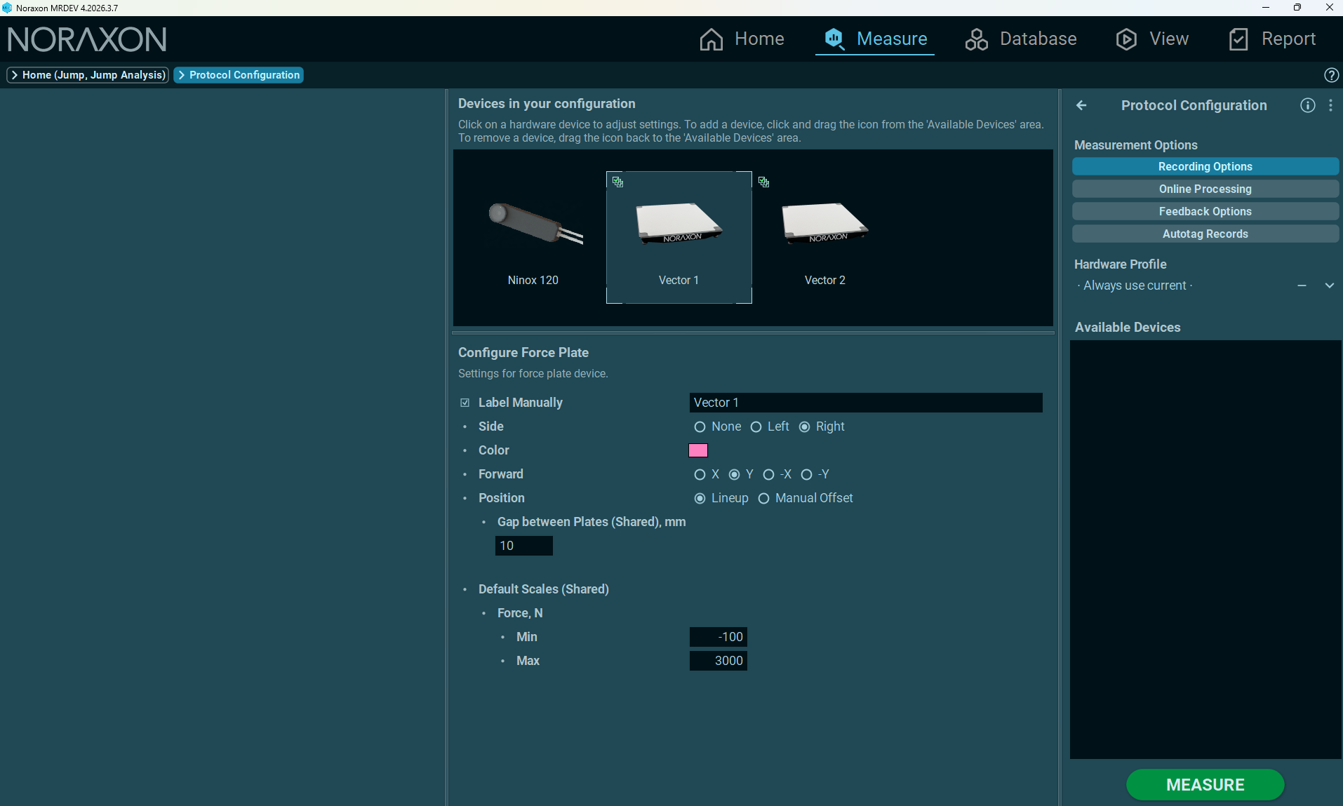
In the Protocol Configuration for your new or existing protocol, add the Vector Force Plates and (optional) camera. Configure the relevant settings for left/right force plate and force plate orientation.
NOTE: This setup is described in more detail in the video below.
Step 3:
Then follow the steps in the video below to add Force Vector Overlay feedback.
Step 4:
Select MEASURE.
Note: Force plates are zeroed automatically during activation. They require no further calibration.
NOTE: It is important that the subject not stand on the force plates during activation. If someone is standing on the force plates during the activation process, their body weight will be zeroed out.
When you are ready, click RECORD.
Record your signal based on predetermined protocols.
After performing desired movements in the recroding, click Stop and Save.
Select Save & measure again (to immediately record again using the same protocol) or Save & View (to immediately view the record and generate a report) after typing your chosen record name.

Viewing a Record
To view a previously-recorded record, select the Database tab. Records are organized by Subject name and any applied Tags. Double click on the record of interest to view the record for playback or prepare for reporting.
Analysis & Reporting
Several pre-installed reports are available for use within the Report screen. To access the Report screen, first open a record from the Database, then select the Report Menu on the right-hand toolbar.
Reports are sorted in eight major tab sections. The accessibility of these tabs is dependent upon the equipment and modules installed.
- myoMUSCLE – for EMG and other biomechanical sensor records
- myoMOTION – for IMU-based 3D kinematic records
- myoPRESSURE – for pressure distribution and gait analysis records
- myoVIDEO – for video analysis records
- myoFORCE – for force and isokinetic analysis records
- myoANALOG – for analog records
Quick Analysis – default report for the Viewer-based Quick Analysis
The reports most commonly used for force plate analysis with 1D Vector Force Plates are the following:
- Jump Analysis (used for bilateral jump analysis)
- Unilateral Jump Comparison (usied for single leg jump analysis)
- Force Plate Balance (used for balance protocols)
Report formatting can be edited to fit the needs of the user. For additional details on customizing reports, visit our 🔗Knowledge Base.
Jump Analysis
The Vector 1D force plates support automated jump detection and analysis for several vertical jump types:
- Countermovement Jump (bilateral and unilateral)
- Squat Jump (bilateral and unilateral)
- Drop Jump (bilateral and unilateral)
- Jump Landings (bilateral and unilateral)
- Hopping (bilateral and unilateral)
For more information on how to perform each jump type and record then in MR, as well as the avaialble jump parameters and reporting options for jump analysis, visit the separate guides linked below.
Troubleshooting & Fault Diagnosis
Symptom: The PC does not recognize the Vector Force Plates.
Possible reason:
The USB cable is disconnected or loose.
The USB driver is not installed.
Solution:
Check the USB cable connection at the computer.
Check the Device Manager for USB driver errors and re-install the MR software to update drivers.
Symptom: The data coming in through the force channels is nonsensical, or the force plates don’t start, despite being shown as available.
Solution:
Multiple devices plugged into the computer share the same driver type (FTDI drivers).
These devices are:
- Bertec devices
- Zebris devices
Solution:
If one of the devices listed is plugged into the computer at the same time as the Vector force plates, unplug those devices.
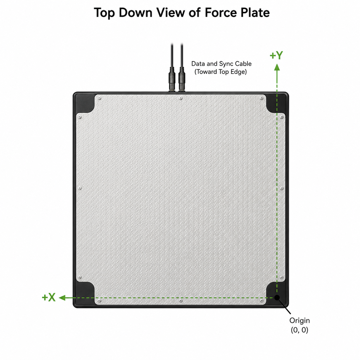
Coordinate System
The coordinate system for the Vector force plate is indicated as below.
Technical Specifications
MEASUREMENT & PERFORMANCE
- Measurement Range: 11,768 N total (2,942 N per sensor)
- Overload Capacity: 150% per sensor
- Non-linearity: +/-0.02% FS
- Combined Error: 0.03%
- Sensitivity: 2mV/V +/-0.25%
PHYSICAL CHARACTERISTICS
- Dimensions: 61 x 61 6 cm (24 x 24 x 2.4 in)
- Weight: 14 kg (31lb)
SIGNAL & DATA ACQUISITION
- Sample rate: 1,000 Hz
- Resolution: 16-bit
CONNECTIVITY & SYNCHRONIZATION
- Interface: USB (Power & Data)
- Synchronization: +/- 5V TTL (3.5 mm jack)
FAQs and Troubleshooting
Q: Can the Vector force plates be used for change of direction, cutting, and other horizontal jump analysis?
A: No. The Vector force plates provide vertical ground reaction force data only, making them unsuitable for applications requiring the analysis of horizonal or shear forces.
For any horizontal or change of direction analysis, contact your Noraxon Rep about 3D force plates.
Learn how to use 3D force plates for change of direction analysis at the link below.
🔗How to Analyze Horizontal Jumps and Change of Direction with 3D Force Plates