Introduction: What is the Translation Toolbox?
The Translation Toolbox is a feature within the Noraxon MR software that allows users to extract translational motion metrics such as speed and displacement from IMU-based recordings.
Traditionally, biomechanical analysis has focused on angular metrics like joint angles, which are valuable for understanding movement strategy and coordination. However, translational metrics—such as how far a person walks or how fast a limb moves—are essential for evaluating task performance and functional outcomes. For example, in sports science, a baseball pitcher’s hand speed at ball release is an important outcome metric. In clinical assessments, walking speed can indicate mobility impairments.
With the Translation Toolbox, users can extract richer, outcome-focused data from IMUs beyond posture and joint angle analysis, thanks to advancements in hardware and signal processing. It is possible to use the Translation Toolbox with as little as a single IMU sensor, making biomechanical analysis more accessible even in resource-constrained environments.
Why Translation Matters in Biomechanics
Biomechanics is often divided into understanding movement strategy (process metrics) and movement outcomes (outcome metrics). While angular metrics such as hip or elbow flexion angles describe how a movement is performed, they do not capture the movement’s real-world outcome. Translational metrics like speed and distance provide this crucial context.
Examples of outcome-focused translation metrics include:
- Horizontal hand velocity in pitching
- Walking speed in gait analysis
- Vertical pelvis displacement in running or jumping
Understanding the relationship between movement strategy and outcome is critical. Two individuals may exhibit similar technique but very different outcomes, or vice versa. By integrating translation metrics, users can gain a complete picture of both how a task is performed and what it achieves.
How IMUs Estimate Translation
Let’s start with an overview of the two primary methods of estimating translation with IMUs: Forward Kinematics and Strapdown Integration. Before getting into the process for Strapdown Integration methods embedded in the Translation Toolbox, it will be helpful to understand the Forward Kinematics method as well.
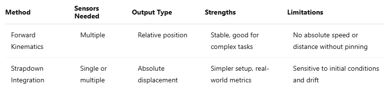
Forward Kinematics: This method connects multiple IMUs via a kinematic chain and calculates the relative translation between body segments. It requires accurate segment lengths and body model calibration. Forward Kinematics enables metrics like stride distance relative to the pelvis using a floating model, and can also estimate absolute travel distance using a pinned model.
Forward Kinematics — Floating Model:
- There is no “floor” or external world.
- Requires body model calibration and scaling.
- Body landmark translations are relative to a body-based reference.
- Enables metrics like stride out distance, but not travel distance or overground speed.
Forward Kinematics — Pinned Model (“Floor mode” enabled)
- Foot contact intervals are detected for both feet.
- The foot contact is pinned as a stationary reference on the ground.
- The “pin” is swapped to the other foot when it makes the next contact.
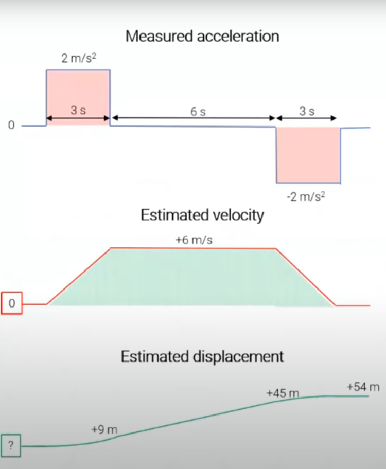
Strapdown Integration: This method converts raw acceleration data to velocity, then integrates velocity to obtain displacement. Historically, strapdown integration was limited due to drift errors, but modern hardware and software improvements have made it more viable, especially for shorter, well-controlled tasks. It is particularly effective when using one IMU, offering a simpler alternative to multi-sensor setups.
Here are the basics:
- A single point is tracked in space.
- Acceleration is integrated over time to achieve velocity
- Velocity is integrated over time to achieve displacement
- **Requires initial conditions for displacement and velocity to be known or assumed!
Below is a table summarizing the key takeaways for using forward kinematics based translation estimation vs strapdown integration.
Initialization for Strapdown Integration: Key for Accurate Results
Velocity Initialization
Velocity initialization is crucial for strapdown integration. Unlike displacement, which can start from any arbitrary value, velocity must be accurately initialized because errors in velocity accumulate over time and cause drift in the displacement estimate. The standard approach is to capture a period of stillness before and/or after the movement. During this stationary phase (typically 1–2 seconds), the velocity is assumed to be zero. If no stationary interval is present both at the beginning and at the end of the activity, strapdown integration fails.
- The solid line in the graph on the right shows the estimated displacement when velocity is accurately initialized to zero in absolute terms..
- The dotted line in the graph on the right demonstrates how offsets in velocity accumulate in the displacement (drift error).

Displacement Initialization
Displacement initialization is more flexible. Since displacement values are not used in further calculations, users can assign any initial value, typically zero. This is particularly useful when comparing against third-party systems. Integration can be performed forward or backward from any chosen point, including the middle of the trial.
Initial displacement values are arbitrary (often zero)
We can also integrate backwards, so initial values can be at the end of the task (0 m estimated at the end).
Initial values can also be somewhere in the middle (-100 m estimated at the middle).

Practical Tips
- Include rest intervals with minimal movement at the beginning and end of each task.
- Prefer foot sensors when analyzing gait or running.
- For non-foot segments, keep analysis intervals short:
-
< 20 seconds for low-intensity activities
-
< 10 seconds for high-intensity rotational activities
- Choose protocols with same start and end positions (zero-displacement) when possible.
How to Use the Translation Toolbox in MR
Now that we’ve covered in-depth how strapdown integration works, let’s discuss how to use it in the MR software.
Step 1: Accessing the Translation Toolbox:
To access the toolbox, navigate to the Motion Capture section and select Translation Toolbox.
Step 2: Mode Selection:
You can choose from the following options:
- Segment Linear Motion (Single Sensor): Generate horizontal and vertical displacement, velocity, and distance signals from a sensor using strapdown integration.
- Center of Mass Linear Motion:
-
Foot-Based: Estimate horizontal center of mass displacement, velocity, and speed using one or more foot-mounted IMUs
-
Model-Based: Estimate horizontal and vertical center of mass displacement, velocity, and speed using forward kinematics from the biomechanical model.
Using Single Sensor — Segment Linear Motion Translation
Step-by-Step:
- Select the IMU sensor (e.g., hand, pelvis).
- Highlight the timeline interval of interest on the timeline.
- Click Set Interval to define the analysis window.
Note: For best results, use shorter intervals (under 10 seconds) when generating displacement signals.
4. Click PROCESS to create signals.
Apply horizontal and vertical closed-loop drift correction or other drift management settings if valid.
- Zero Horizontal Displacement: Assumes the sensor returns to the same horizontal postion at the end of the interval, as used at the beginning of the interval.
- Zero Vertical Displacement: Assumes the sensor returns to the same vertical height at the end of the interval, as used at the beginning of the interval.
Correct Drift During Shuttle Activities: Improves displacement accuracy for activities that include linear bidirectional movement. Assumes the sensor turns at the same horizontal position after each shuttle. Use for activities involving gait/running or other activities covering the same distance back and forth.
Correct Vertical Drift During Gait: Automatically applies vertical drift correction during detected gait activities. Only available for spine segments: Pelvis, Upper Spine, and Lower Spine.
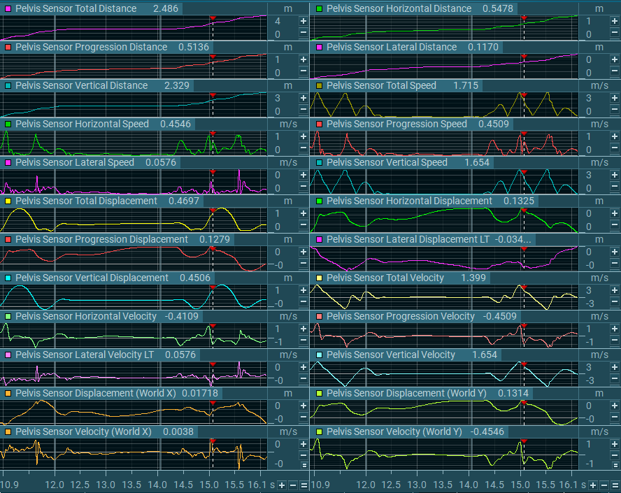
Created Signals:
The following signals are available in the newly created Segment Motion (‘segment’) tab:
Note: The example signals below reference the Pelvis segment.
Distance Signals:
- Pelvis Sensor Total Distance
- Pelvis Sensor Horizontal Distance
- Pelvis Sensor Vertical Distance
- Pelvis Sensor Progression Distance
- Pelvis Sensor Lateral Distance
Displacement Signals:
- Pelvis Sensor Total Displacement
- Pelvis Sensor Horizontal Displacement
- Pelvis Sensor Vertical Displacement
- Pelvis Sensor Progression Displacement
- Pelvis Sensor Lateral Displacement LT
- Pelvis Sensor Displacement (World Y)
- Pelvis Sensor Displacement (World X)
Velocity Signals:
- Pelvis Sensor Total Velocity
- Pelvis Sensor Horizontal Velocity
- Pelvis Sensor Vertical Velocity
- Pelvis Sensor Lateral Velocity LT
- Pelvis Sensor Progression Velocity
- Pelvis Sensor Velocity (World X)
- Pelvis Sensor Velocity (World Y)
Speed Signals:
- Pelvis Sensor Total Speed
- Pelvis Sensor Horizontal Speed
- Pelvis Sensor Vertical Speed
- Pelvis Sensor Latera Speed LT
- Pelvis Sensor Progression Speed

Single Sensor — Segment Linear Motion: Use Case Examples
- Analyze hand speed during pitching
- Evaluate jump height
- Measure pelvis displacement in gait or running
For full use-case tutorials on single sensor strapdown integration, view Translation Toolbox Use Case Tutorials (LINK).
Using Center of Mass Linear Motion — Foot-Based Translation
Step-by-Step:
- Use foot-mounted IMUs.
- Highlight the timeline interval.
- Click Set Interval to define the analysis window.
- Click PROCESS to create signals.
Apply horizontal closed-loop drift correction if valid:
- Zero Horizontal Displacement: Assumes the foot returns to the same horizontal position at the end of the interval.
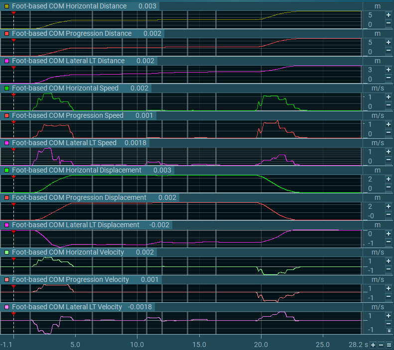
Created Signals:
The following signals are available in the newly created Foot-Based COM tab:
Distance signals:
- Foot-Based COM Horizontal Distance
- Foot-Based COM Progression Distance
- Foot-Based COM Lateral Distance
Displacement signals:
- Foot-Based COM Horizontal Displacement
- Foot-Based COM Progression Displacement
- Foot-Based COM Lateral LT Displacement
Velocity signals:
- Foot-Based COM Horizontal Velocity
- Foot-Based COM Progression Velocity
- Foot-Based COM Lateral Velocity LT
Speed signals:
- Foot-Based COM Horizontal Speed
- Foot-Based COM Progression Speed
- Foot-Based COM Lateral Speed LT

Center of Mass Linear Motion — Foot-Based Translation: Use Case Examples
- Estimate walking or running speed
- Measure overground distance covered
For full use-case tutorials on multiple sensor – foot sensors integration, view Translation Toolbox Use Case Tutorials (LINK).
Using Center of Mass Linear Motion — Model-Based Translation
Step-by-Step:
- Highlight the interval of interest.
- Choose whether to enable Zero Height (zeroes vertical position at the start).
- Click Set Interval to define the analysis window.
- Click PROCESS to create signals.
Apply vertical constraint to Set Initial Height to Zero if applicable – Zeroes vertical position at the start of the analysis interval. If disabled, the subject’s body height is taken from the model.
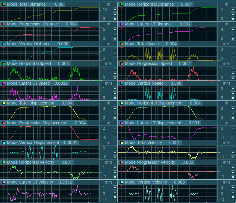
Created Signals:
The following signals are available in the newly created Model-Based COM tab:
Distance signals:
- Model Total Distance
- Model Horizontal Distance
- Model Progression Distance
- Model Lateral LT Distance
- Model Vertical Distance
Displacement signals:
- Model Total Displacement
- Model Horizontal Displacement
- Model Progression Displacement
- Model Vertical Displacement
- Model Lateral LT Displacement
Speed signals:
- Model Total Speed
- Model Lateral LT Speed
- Model Horizontal Speed
- Model Vertical Speed
- Model Progression Speed
Velocity signals:
- Model Total Velocity
- Model Horizontal Velocity
- Model Vertical Velocity
- Model Lateral LT Velocity
- Model Progression Velocity
Using Center of Mass Linear Motion — Model-Based Translation: Use Case Examples
- Measuring speed or displacement of the entire body model
For full use-case tutorials on Multiple Sensor-Model Translation methods, view Translation Toolbox Use Case Tutorials (LINK).
Definitions for Translation Toolbox Signals
Distance
Represents the total path length traveled, accounting for all movement. Distance values accumulate regardless of direction changes. Examples include:
- Model Total Distance: The full length of the path traveled in 3D space.
- Model Horizontal Distance: Path length traveled within the horizontal plane.
- Model Progression Distance: Path length traveled along the defined progression direction.
- Model Lateral Distance: Path length traveled laterally
- Model Vertical Distance: Path length traveled vertically.
Displacement
Represents the straight-line change in position between two points, in the specified dimension or direction. Displacement does not accumulate; it is the net difference from start to end. Positive values indicate movement in the positive direction from the initial position and negative values indicate negative change from the initial position. Examples include:
- Model Total Displacement: Straight-line change in position in 3D space.
- Model Horizontal Displacement: Net change within the horizontal plane.
- Model Progression Displacement: Net change along the progression direction.
- Model Vertical Displacement: Net change in vertical position.
- Model Lateral Displacement LT: Net change laterally, relative to the left-right axis. A positive value indicates displacement change to the left of the body, and a negative value indicates displacement change to the right side of the body.
Velocity
Represents the rate of change of displacement with respect to time in the specified dimension or direction. Velocity is a vector quantity, meaning it includes both magnitude and direction, and can be positive or negative. Examples include:
- Model Total Velocity: Rate of change of total displacement in 3D space.
- Model Horizontal Velocity: Velocity within the horizontal plane.
- Model Vertical Velocity: Velocity in the vertical direction.
- Model Lateral Velocity LT: Velocity along the lateral (left-right) axis. A positive value indicates velocity direction change to the left of the body, and a negative value indicates velocity direction change to the right side of the body.
- Model Progression Velocity: Velocity along the progression direction.
Speed
Represents the magnitude of velocity, without regard to direction. Speed values are always positive and reflect how fast an object is moving. Examples include:
- Model Total Speed: Magnitude of total velocity in 3D space.
- Model Lateral Speed: Magnitude of lateral velocity.
- Model Horizontal Speed: Magnitude of horizontal velocity.
- Model Vertical Speed: Magnitude of vertical velocity.
- Model Progression Speed: Magnitude of velocity along the progression direction.
Progression
The progression direction is defined in the settings for the motion model in the Model Options > Model Outputs menu. In model outputs, progression refers to the primary movement direction defined in the model’s coordinate system for the task. Below are the progression mode selections available.

Translation: Progression is defined by the smoothed direction of overground translation. If floor translation is disabled or insufficient, progression reverts to the root segment method.
Root Segment: Progression is defined by the smoothed direction of the Pelvis or else the Upper Spine.
Bidirectional: Progression is defined by the direction faced by the subject during the static calibration pose, but flips 180 degrees if the subject faces the opposite direction.
Calibration: Progression is defined by the direction faced by the subject during the static calibration pose.
NOTE: The progression direction is depicted by the yellow arrow in the image to the left.
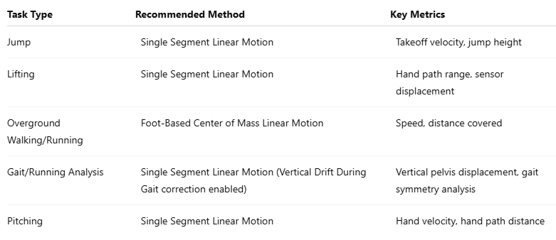
Common Use-Case Scenarios Recap
Below are some recommended use-case scenarios for the Translation Toolbox, with the method and key metrics indicated.
Full use-case tutorials are available in the Translation Toolbox Use Case Tutorials (LINK) guide.
Summary and Recommendations
The Translation Toolbox provides a streamlined method for extracting translational motion metrics from IMUs. Whether using a single sensor or a full-body model, users can now evaluate speed and distance metrics alongside traditional kinematic data. The accuracy of these estimates depends largely on proper initialization, controlled protocols, and thoughtful sensor placement.
For best results:
- Always include stationary intervals for velocity initialization
- Use closed-loop constraints when valid
- Keep analysis intervals short and controlled
- Leverage foot sensors for gait tasks when possible
With proper setup, the Translation Toolbox allows for real-world biomechanical analysis of task performance and functional outcomes in clinics, sports, and research environments