This guide explains how to integrate the Biodex Isokinetic Dynamometer within the MR software environment. It covers the hardware required, step-by-step setup in the software, and the types of reports available for data analysis. In addition, you’ll find troubleshooting tips to address common setup and communication issues, ensuring a smooth and reliable workflow from data collection to reporting.
Required Hardware
The following hardware is required for integration of your Biodex isokinetic machine into the MR software.
Figure 1: Noraxon Analog Input System (part #222B)

Figure 2: DB25 to DB15 Biodex to AIS cable (part #222E)

Installing the Hardware
Step 1: Connect the AIS to the Biodex through the Remote Access port using the Biodex to AIS cable.
Step 2: Connect the AIS to the PC via the USB A to B cable.
Step 3: Open the Hardware Setup in MR, insert the AIS device, and choose “Detect.”

Setting up a Protocol and Scaling Analog Torque, Velocity, and Position Channels
Step 1: Select any Application, then create a new Protocol. For more details on general protocol creation, reference the guide linked below.

Step 2: In the Protocol Configuration, add the AIS device, then enable channels 1, 2, and 3.
Note: If you are synchronizing your torque, angle, and velocity data from the Biodex with EMG, you can also add your EMG system here, if it was set up ahead of time.

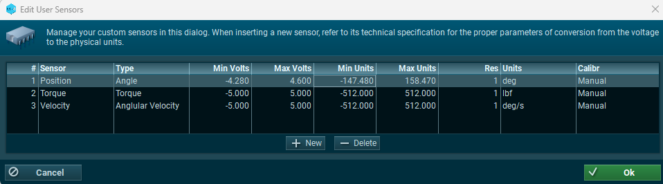
Step 3: Select the User-defined sensors tab and click “Insert/Delete Sensors” to add new sensor channels. This is where the Torque, Velocity, and Angle channels will be added.

Step 4: Add new sensors to the list, matching the type and units for the Position, Velocity, and Torque channels below.
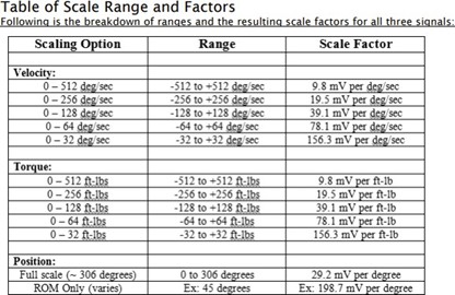
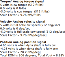
Note: the analog signals for the Biodex range from -5 to +5 volts for Velocity and Torque, and -4.28 to +4.60 volts for Position. With the standard Remote Access option available on a System 4 or 3 Rev 2, all analog output signals are at full scale (full scale being the default). Full scale torque, or example, is -512 to +512 ft-lbs, for a total range of 1024 ft- lbs.
For refernece, the analog scaling factors from the Biodex User Manual are shown below. If your machine is configured differently than the default, you may be required to modify the scaling factors to meet the range specified in your machine’s settings.
Step 5: Once the user-defined channels are added, assign each sensor to Channels 1-3 by double-clicking on the sensor in the user-defined sensors list when the desired channel in section 2 is highlighted. The channels are assigned as follows:
Channel 1 = Torque
Channel 2 = Velocity
Channel 3 = Position
Once assigned, the Sensor, Amplitude, and Units for each channel will be automatically filled in.

Step 6: Name channels 1-3 manually in the sensor selection list.

Recording Data
Step 1: Start a measurement in the Biodex software to start streaming through the analog outputs and into MR.
Step 2: Begin recording in MR by clicking MEASURE from the Home page or Protocol Configuration.
Step 3: Check the signals and click RECORD when ready to record.
Step 4: When finished, click STOP and save your data using one of the save options listed when the recording has finished.
Data Analysis
A report for the Biodex are available pre-built into the MR software. If you assigned a report when you created the protocol, the report will be automatically generated. The “Biodex Isokinetics Knee” report is designed for the analysis of synchronized measurement of EMG and biomechanical output signals (torque, angle, velocity) during any isokinetic activity. The isokinetics output signals need to physically connected and integrated into the EMG recording, at minimum the torque and the position signal has to be recorded. The report setup depends on the given Isokinetics device and the predefined report setup may need some adjustments to the given isokinetics system.
Period Definition:
Mode: Min/Max by trigger channel, Min to Min with event (based on isokinetics angle signal)
Automatic period definition is based on a trigger detection algorithm, which typically uses the angle or velocity input signal. These settings can be adjusted in the next screen after selecting this report or via operating “Re-analyse” in the report preview menu. At least one repetition cycle of extension / flexion, ab- / adduction, in – / out rotation must be found. Detected periods are indicated by yellow (first phase) and blue (second phase) bars in the Viewer screen
Recommended processing:
Bipolar (raw) EMG signals need to be rectified and smoothed with a moving average or RMS algorithm with typically 50 to 100ms time constant. Bipolar torque curves should be rectified.
Report contents:
1. Page: Subject header, Averged Curves screen with Mean and Peak value bar graphs
2. Page: Subject header, time domain changes bar diagram for Mean EMG and torque/angle for both motion phases (e.g. knee extenstion/flexion), time domain statistics table
Analysis and interpretation:
The main purpose is to document the typical activation pattern and firing characteristics within each repetition cycle of the isokinetic activity (e.g. extension – flexion, abduction – adduction, in- / outward rotation, etc.). Angle, velocity or direction signals derived from the isokinetics device are used to time normalize and average EMG patterns for comparisons with the average torque output curve. The second page of the report provides a time domain analysis of the amplitude mean and peak values in a parameter trend diagram. This analysis reflects the changes in the neuromuscular recruitment within the recorded test or training set.
An example report is shown below. All reports in MR can be customized to show desired and relevant metrics for an individual’s project. 🔗Request support to learn more about report customization for this application.


Troubleshooting and FAQs
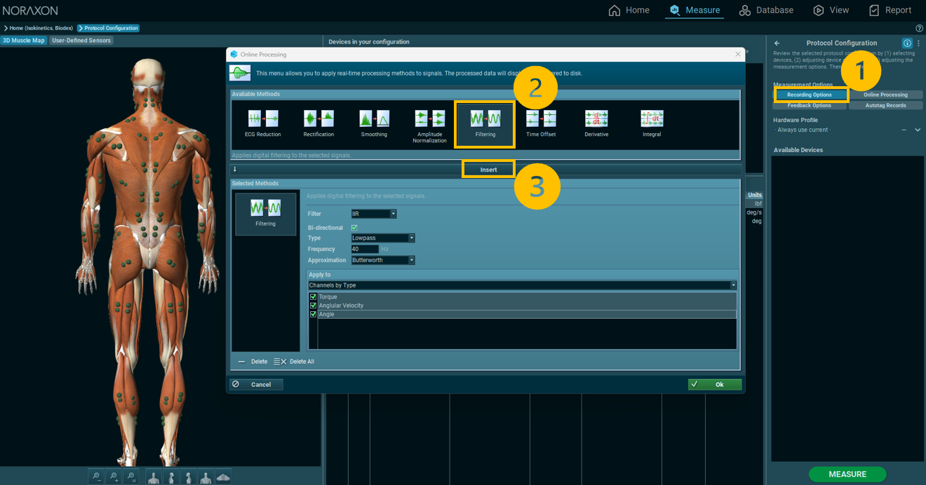
Q: My analog signals are very noisy due to high frequency noise in the surrounding environment. How do I filter my signal to achieve reduced noise?
A: Since all of the analog data comes in at low frequencies (below 40 Hz), a low pass IIR filter with a 40 Hz cutoff can be applied either in post processing or within the Protocol Configruation through the Online Processing tools.
To learn how to add this filter to the real-time capture, follow the steps below to include the lowpass filter in the Protocol Configuration. For more information on how to apply filtering after data collection, reference the article below to learn more about Noraxon’s Signal Processing Tools.
🔗Signal Processing Tools Tutorial
(Click on the image below to enlarge)
Q: My velocity signals appear to be swapped between the positive and negative axes. How do I account for this in the setup?
A: Some machines may have the velocity or torque channels flipped in polarity. To account for this in MR, swap the min/max voltage directions in the user-defined sensors setup.
Velocity or Torque:
- Min V: +5.0
- Max V: -5.0
- Min value: -512
- Max value: +512
