FAQs
The Skin Preparation video tutorial demonstrates the procedure. For additional information, please refer to the ABC of EMG Manual, Skin Preparation section, page 15.
We have found that an abrasive skin-prepping gel for ECG and EEG use, such as NuPrep™, usually solves the problem.
Please refer to the cleaning instructions from the each hardware manual as shown below:
Cleaning Safety Precautions When Cleaning
WARNING Only use a damp cloth with mild soap and water or isopropyl alcohol to clean the bottom of the Sensors. Do not immerse Sensors in any water or liquid. Cleaning by Users For sanitary purposes, it is advisable to clean the bottom of the Sensors on a regular basis. The Sensors can be cleaned with a cloth slightly dampened with a solution of mild soap and water or isopropyl alcohol. The Sensors are not constructed to withstand repeated application of any disinfectant solution. Likewise, the Sensors are not warranted against exposure to any of the conventional forms of sterilization. Users wishing to utilize this equipment in a sterile environment, such as an operating theater, should consult Noraxon for other options.
The Gyro sensors should be reset on a monthly basis. Instructions can be found in the Zero Gyros section of the MyoMotion Hardware Manual, section 8.3. Make sure to use this feature only when the sensors are in a magnetically clean and stationary environment (i.e. no metal nearby / stable). For additional information, please contact our technical support team. Hover over the ‘Support + Learn’ tab and click on the ‘Support Request’ option.
General maintenance and upkeep of your treadmill is required to maintain pristine performance. It is recommended to routinely clean the treadmill surfaces and periodically lubricate and re-center the running belt.
If your treadmill is the Phystread or Kintread model, refer to the h/p/cosmos Treadmill User Manual. Information regarding lubrication of the running belt begins on page 118. Information for centering the belt begins on page 127. Information for treadmill cleansing begins on page 132.
If your treadmill is the SciFit model, refer to section 4.1 of the SciFit Operations Manual for general maintenance information. Refer to section 8.1 for documentation of potential issues that you may be having.
If your treadmill is the Gaitread model, please submit a support request under the ‘Support + Learn’ tab. A member of the Noraxon team will assist you as soon as possible.
You can find the computer requirements for MyoResearch3 here. These specifications are subject to change without notice due to the volatility of the computer industry. It may be assumed that systems shipped by Noraxon will meet or exceed these specifications. Systems quoted with these specifications are good for three months after the date of the quotation.
This often occurs as a result of the file size limit (2GB) being exceeded. Check that the storage drive that MR3 saves to has not run out of memory.
- Can be accompanied by a message stating: “Error: write to file”
Issue is likely due to Ninox file sizes, however it is recommended to reach out to the Noraxon Support team to narrow down the problem. Hover over the ‘Support + Education’ tab and click on the ‘Support Request” option.
OpenGL errors are always related to the graphics card. To fix it, make sure your power and graphics card settings are configured according to our Ninox 300C manual. You can find a video here showing how to adjust these settings.
Be sure your graphics card meets our general computer specification requirements.
The long wire on channel 1 is called the reference/ground. This reference/ground must be on the subject to get valid data.
In the past, the recommendation was to place the reference lead on a bony prominence; however, with today’s technology you can place the reference lead anywhere on the body.
A “Snap Lead Extender” (part # SLE) is available for purchase in 3 lengths: 12” (30.5 cm), 24” (61 cm) and 36” (91.4 cm). For more information or to order this product, please email Noraxon’s customer service at info@noraxon.com or call (480) 443-3413 (US/Canada customers may call 1-800-364-8985).
The numbers on the 2-snap or pinch end Active Pre-amp leads are only labels. You can plug in the 2-snap or pinch end lead into any available analog connector.
There are several possible reasons why you are getting an irregular signal. 1) Electrode problems, such as dried-out or expired electrodes, inadequate skin preparation or electrode coming off. 2) Unused leads that are connected to the Noraxon System are not “shorted out.” This allows noise in the environment to affect the signal of the leads on the subject’s body. 3) Occasionally – The pre-amp lead is not functioning properly. 4) Rare – Analog Connector on Noraxon System is not functioning properly. For detailed troubleshooting techniques, please refer to the document Troubleshooting Irregular EMG Signals.
Check the toggle switch on the front of the MS1400A – is it on “cable” or “BNC”? Switch it to the auxiliary source you are using. In the channel setup in MRXP, the Aux inputs are channels 17-20.
The video tutorial (no audio) myoSYSTEM 1400A USB Driver Installation explains how to do it.
Even though the charging light on the myoTRACE 400 is not on, in most cases it is still charging. In order for the charging light to illuminate, you will need to plug the charger first into the myoTRACE 400, then into the wall outlet. For more information, please refer to the myoTRACE 400 manual.
When the battery is fully charged but the myoTRACE 400 display does not show 100%, information in its fuel gauge (charge indicator) is outdated and must be revised. The battery fuel gauge is able to learn new settings automatically. To do this you will need to fully discharge and recharge the battery at least two times. To discharge the battery, turn on the myoTRACE 400 and let it run until it shuts off. (A convenient way to discharge the battery is to let the myoTRACE 400 run overnight.) It will take about three to four hours for the battery to recharge. Repeat this a second time. If this solution does not solve the problem, please email Noraxon’s technical support at support@noraxon.com or call (480) 443-3413 (US/Canada customers may call 1-800-364-8985).
This error is usually resolved by installing a patch. If you are using myoRESEARCH® XP™ 1.06, you will need patch 1.06.78. If you are using 1.07, you will need patch 1.07.05. These patches are available on our software download page. MRXP Software Patches
An Activation Key is displayed in myoRESEARCH® XP™ in the same window that requested the Activation Code. Email Noraxon’s customer service at info@noraxon.com or call (480) 443-3413 (US/Canada customers may call 1-800-364-8985) with your Activation Key. The Activation Code you receive will only work for the computer with the Activation Key you gave Noraxon. Enter this code in the myoRESEARCH® XP™ window and click “Activate”.
Try the following suggestions:
1) Be sure to enter the “-”.
2) The letter “O” is not used in the key or code; only the number “0” (zero) is used.
3) Recheck the characters “B” and “8” since they look alike.
4) If you called Noraxon for the code, miscommunication may have happened. Try emailing the Activation Key to info@noraxon.com.

Through our Student License Program, you are given a fully unlocked, FREE 6 month license for in-depth analysis: every feature and report is available. In addition, you offered unlimited access to our technical support team.
To request an academic license, please fill out the Academic License Request Form. You will need an email address associated with a University and an Administrator’s MR3 license ID.
MVC is an abbreviation for Maximal Voluntary Contraction. Usually, static resistance is used to create a “maximum” contraction value for that muscle. The MVC value is then used to convert the muscle uV values into a percentage of the MVC. For more information, please refer to the ABC of EMG Manual section Signal Processing – Amplitude Normalization, pages 30-35.
In SEMG analysis, the amplitude of the data are strongly influenced by many detection conditions, such as electrode placement, changing environmental conditions, different subjects, etc. If you plan to compare across recording sites, across patients, across sessions or to a published standard, normalization is necessary. For more information, please refer to the ABC of EMG Manual section Signal Processing – Amplitude Normalization, pages 30-35.
1) Identify and perform a standardized isometric procedure for a defined time period.
2) The SEMG activity is averaged for a fixed time period to find the highest AVERAGE peak value. This mean becomes the normalization reference value for the muscle.
3) Perform the evaluation task. The clinical task mean is divided by the MVIC mean and multiplied by 100 to find the Normalized Value. Baseline Value ÷ Maximal Effort × 100 = Normalized Value (expressed in %MVC). For more information, please refer to the ABC of EMG Manual section Signal Processing – Amplitude Normalization, pages 30-35.
Please refer to the ABC of EMG Manual section Signal Processing – Amplitude Normalization, pages 30-35.
Real-time processing is recommended to calculate the MVC. The MVC in Real-time video tutorial demonstrates how to create and apply the MVC in real time in MRXP. The document MVC Normalization in myoRESEARCH XP: Post-Process Method describes how to calculate the MVC after recording the data.
The MVC values are saved in a file. A “stack” is a computer-programming term that indicates the method used to store the data. Every time you save data to the “MVC Stack,” the current values are replaced with the new values.
Note: The MVC stack values will be updated according to the muscle/channel. They are not saved differently for different subjects.
No, you must have myoVIDEO and a reference camera set up in order to view the force vector. Without a reference video, the technology is not possible.
You can access the force vector overlay using myoVIDEO and any force plate that is coming into MR3 via a supported digital input or any force plate integrated via the Analog Input System (AIS).
Noraxon has a de-magnetization tool that should fix this problem. A Noraxon employee can remotely sign into the customer’s computer and do this for them. Please fill out a support request: Hover over the ‘Support + Learn’ tab and click on support request.
Treadmill mode can be used if the person plans to remain on the force plate for a long period of time. If this is the case, then it is important that the person wearing the system calibrates facing the same direction as the jump (or other task) and does not impart any rotations during the measurement. However, if the majority of the environment is clean magnetically, then you should not have any problems calibrating without treadmill mode in a “clean” area then performing the task on the force plate. You may have to re-calibrate due to impact conditions but it is likely that the force plate itself will not affect the data as long as the person does not remain on the force plate for extended amounts of time.
First, check that “Acceleration Data” is selected in the Hardware Setup for the myoMOTION receiver. Open the Home tab of MR3. Select “Hardware Setup” in the right toolbar. Drag the myoMOTION receiver into the Active Devices field (if not already) or double click on its image to open its hardware setup. Select the checkbox next to “Accel. Data” in the bottom field of the myoMOTION hardware setup. See image below: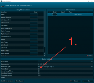
There is currently not an option for calibrating in a supine lying position. If all actions were to be performed in this position, it is possible to use the standing straight calibration while lying down. It is important to note that it may be difficult to find a clean calibration location while lying down. Also, it would not work if the subject then stood up to walk around. This would lead to muscular dislocation of the sensors and the data would be unusable. The movement of interest needs to be one in which the subject stays in an orientation similar to the calibration position.
There has been a failure to transmit the data from the sensors to the receivers in real-time. If you purchased your myoMotion sensors in 2015 or later, they should be capable of recovering this data once the trial has come to completion(“lossless”). To verify if your sensors are lossless or not, submit a support request with the serial number of your sensors. Below are some steps to help prevent the data loss from happening:
- If you are collecting with multiple systems, make sure that each system is collecting on different RF channels. To do this, click on the home tab on the top left corner of the MR3 page. Then, click on the hardware setup button on the top right corner of the page. Then, double click on each of the devices in use and verify that they are using different channel names.
- Make sure there is a clear path between the receiver and the sensors. Items such as computers can cause RF interference and cause data loss.
- If the loss is still occurring, try a new RF channel. If there is too much traffic on the selected RF channel, significant data loss may occur. In order to avoid this loss of data, switching the channel to another frequency may solve the problem.
- Move the receiver closer to the individual who is wearing the sensors without moving closer than 0.5 meters. The optimal distance between the sensors and the receiver is approximately 1 meter.
Yes, MR3 does have a report that can tell you muscle firing patterns. This report is available in the myoMUSCLE Master report section and is named “Standard Timing Analysis”. The report is designed for the EMG onset/offset analysis of reflex studies or other timing related test setups. Based on a threshold definition using the standard deviation of the EMG baseline (3 x SD by default) the onset, offset, and firing order of muscle activity is analyzed and displayed. Alternative threshold definition modes such as percent of local peak activity and using a fixed value are also supported.
The solid green light is an indicator that the sensor’s radio/WiFi communication circuit has been damaged. As there is nothing we can do without opening it up, the device will need to be sent in as an RMA. You can begin the RMA process by filling out the RMA Request Form and sending the malfunctioning device to the following address:
15770 N. Greenway-Hayden Loop #100
Scottsdale, AZ 85260
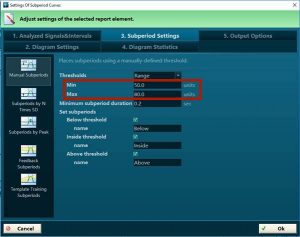
In ergonomics, an MVC-normalized EMG below the 20-30% range means the recorded activity is not critical for worker’s well-being. Below this range is a safe point, and workers can continue performing at that level. To change this, click “Edit Report” in the right toolbar of the Viewer tab and double-click the graph. In the pop-up window, click “3. Subperiod Settings” and adjust the minimum or maximum thresholds as necessary. In the image below, the 20-30% was changed to 50-80% as an example:
There has been a failure to transmit the data from the sensors to the receivers in real-time. If this is the case, some sensors are capable of recovering the data at the end of the trial. Ultium (part #810) and DTS Lossless EMG pre-amp/sensors (part #548) is capable of doing this, however the DTS EMG pre-amp sensor(part #542) is not. Below are some steps to help prevent the data loss from happening:
- If you are collecting with multiple systems, make sure that each system is collecting on different RF channels. To do this, click on the home tab on the top left corner of the MR3 page. Then, click on the hardware setup button on the top right corner of the page. Then, double click on each of the devices in use and verify that they are using different channel names.
- Make sure there is a clear path between the receiver and the sensors. Items such as computers can cause RF interference and cause data loss.
- If the loss is still occurring, try a new RF channel. If there is too much traffic on the selected RF channel, significant data loss may occur. In order to avoid this loss of data, switching the channel to another frequency may solve the problem.
- Move the receiver closer to the individual who is wearing the sensors without moving closer than 0.5 meters. The optimal distance between the sensors and the receiver is approximately 1 meter.
- Use the inSSider WiFi sniffing tool available on our downloads page to determine the best RF channel for your WiFi environment.
Open the record in the Viewer tab. Refer to the ‘Pressure, Gait Mode’ field and press ‘tools’ in the top right. One of the tools that will be displayed is entitled: Exchange foot sides of the current exercise. Select this button to swap the left/right foot contacts.
Please refer to the use the Import/Export to external location option from the database to transfer records between MR3 versions or installations. For additional information, a video tutorial and document on exporting/importing is available upon request. Hover over the ‘Support + Learn’ tab and click on the ‘Support Request” option.
Markers can be added/deleted from the Marker Menu in the Viewer tab. Please refer to the Marker Menu section of the myoMOTION Software User Guide, pages 101-106 or the Online Help tool in MR3. For more information on Marker placement for reports, hover over the ‘Support + Education’ tab and click on the ‘Support Request” option.
Reports are sorted in seven major tab sections in MR3. The accessibility of these tabs is dependent upon the equipment and modules installed:
- myoMUSCLE (Essential, Clinical, Master) – for all myoMUSCLE EMG and sensor records. Refer to pages 106-129 of the myoMUSCLE Software User Guide for more information.
- myoMOTION – for all myoMOTION based 3D kinematic records. Refer to pages 120-141 of the myoMOTION Software User Guide for more information.
- myoPRESSURE – for all pressure related records.
- myoVIDEO – for myoVIDEO 1 and 2 video camera records. Refer to pages 73-82 of the myoVIDEO User Software Guide for more information.
- myoFORCE – for all 3D force plate related recordings. Refer to pages 97-115 of the myoFORCE User Software Guide for more information.
- Quick Analysis – default report for the Viewer based Quick Analysis.
It is recommended that new MR3 users review the myoRESEARCH 3 Introduction Tutorial to learn the general flow of the software. For module-specific quick start guides, please refer to the following:
For additional information, please contact our Support Team for remote training and Q&A. Hover over the Support + Education tab, and submit a Support Request.
Please refer to the myoVIDEO tutorial
Please refer to the video tutorial Copy myoRESEARCH XP data to another PC.
Please refer to the document Copy Data from myoRESEARCH XP
Please refer to the documents How do I do that in MRXP, Backup Data in myoRESEARCH XP and Backup (Copy) Subjects in MRXP
Copy: Use with myoRESEARCH® XP™ data (e.g., backing up MRXP data, copying MRXP data back into MRXP).
Import/Export: Use when you are importing or exporting files from other sources (i.e., not MRXP files). If you want to save the MRXP data to another file type, then use Export and select a file type from the pull-down menu. The process is similar to Importing data from another file type into MRXP.
Please refer to the document How do I do that in MRXP.
The document Copy an Application/Protocol into MRXP explains the procedure with step-by-step instructions.
You must have version 1.06 or higher in order to apply a patch to MRXP. Earlier versions (e.g., 1.03, 1.04, 1.05) do not have this feature.
1) Download the current MRXP patch.
2) Exit from myoRESEARCH® XP™ before installing the patch.
3) Run the “.exe” file that you downloaded and a wizard will help you install the patch. A password is not required to install the patch.
Please refer to the ABC of EMG Manual section Signal Processing – Amplitude Normalization, pages 30-35.
The issue likely stems from the USB connection or the graphics card. Check for the following:
- The wrong cable is being used to connect the camera to the computer or portable lab, or the cable isn’t connected properly/securely. Reach out to support team for guidance.
- ‘USB Selective Suspend’ is enabled in advanced power settings. To disable, search for ‘advanced power settings’ in Windows search bar.
- The USB cable is not plugged into correct port. Ensure that it is plugged into a USB 3.0 port (indicator are the letters ‘SS’, a power symbol, or a lightning bolt).
- Too much traffic is on an individual USB hub. Try unplugging everything but one camera–if this fixes the problem, contact Noraxon Support for permanent solution.
- The specifications for the computer running MR3 are not sufficient for camera/3D graphics requirements. Please refer to the FAQ titled ‘Computer System Recommendations’ under the General System Requirements section for recommended specifications. For more information, read Optimizing Graphics Settings for MR3 and Graphics Card & OpenGL Guide.
- The graphics card driver is not up to date. It is recommended to visit the manufacturer’s website and download most recent version, as the automatic update may not always work (even when accessed from the device manager or driver suite).
If unsolved, contact the support team by hovering over the ‘Support + Education’ tab and clicking on the ‘Support Request’ option.
A high frame rate, which is measured in frames per second (FPS), is a direct trade off to video quality. Therefore the faster (higher) the frame rate, the poorer (lower) the available camera resolutions–unless you spend top dollar on a more powerful camera. If you are not seeing the resolution that you previously seen or if the viewing frame size is incorrect, you can change this in the Ninox settings in Hardware Setup or in the Edit Configuration button in the Home tab. In the setup menu, drop the frame rate and more resolution options will become available. For more information on camera setup, refer to Section 2 of the myoVIDEO Software User Guide, pages 5-13.
The issue occurs when the file size limit of 2GB is exceeded. You should reach out to the support team for assistance. Do this by hovering over the ‘Support + Learn’ tab and clicking on the ‘Support Request” option.
This error occurs when you attempt to access camera settings while the Ninox camera is not plugged into the computer or is not enabled via the Hardware Setup. Please navigate to the Hardware Setup and ensure that the camera you are trying to record with is available in the “Selected devices” section.
Note: If the camera is available but grayed out, try unplugging the camera and plugging it back in.
If the error still occurs after verifying the connection, please make sure the connections on the end that goes to the PC and on the end that plugs into the camera are secure. You can also try plugging the camera into a different USB port.
If you still see the same error, please contact Noraxon Support to help you narrow down the problem. Hover over the ‘Support + Education’ tab and click on the ‘Support Request” option.
This means that the computer is registering the camera as a USB 2.0 device (instead of a USB 3.0 device). The camera is not receiving enough power from the PC to achieve higher frame rates and resolutions.
Make sure the camera is plugged into a USB 3.0 port on the computer (indicated by an “SS” signal or by the color blue on the inside of the port).
If the above solution does not help, there may be a problem with your hardware (cable or camera). Please contact Noraxon Support for more assistance in narrowing down the problem. Hover over the ‘Support + Education’ tab and click on the ‘Support Request” option.
You can use the cost estimate calculator available on the Battery Replacement form. Choose the sensor type for pricing.
DTS EMG/ myoMotion IMU:
- Put the sensors into shutdown mode (Click on the home button in the top navigation bar. Then click on the setup button in the upper right corner of the screen. Then click on the configure device button at the bottom right corner of the hardware setup box. Finally, click the “shutdown sensors” button at the bottom of the settings box.) When the sensors are shutdown they will stop blinking completely. The sensors are reactivated by briefly charging them.
- Place all sensors into the sensor charging station.
- Position all components inside the system travelling case according to their prepared cavities.
- Store sensors away from any magnetic material.
The best way to test would be to charge the sensors fully overnight, start a measurement with them in the morning (with the receiver plugged into power) and sensors simply sitting in the charging block (unplugged). If you notice the sensors start to die in any time frame less than 3/4 hours, you will know they need replacement.
The sensors will go to sleep (stop measuring) if they are out of range of the receiver for 5 consecutive minutes. After the sensors go to sleep it is not possible to recover data as it was never measured. Every time the sensors get back into range they reset this 5 minuter timeout timer. As an example, they can go out of range for 4+ minutes and come back in for a few seconds to reset the timeout timer and then go out for 4+ minutes again. However, the myoMOTION and DTS Lossless functionality was not designed for data logging–it was designed to fill intermittent gaps due to poor wireless conditions. Data recovery can take a very long time for long periods of loss. For true data logging the myoMOTION Datalogger or the DTS Belt Receiver should be used.
DTS EMG/myoMotion IMU:
When in Charger (Charge Indicator – Amber):
1) Steady – Sensor is charging.
2) No LED – Battery fully charged.
When not in Charger (Status Indicator – Green):
1) Flashing quickly – The sensor is either in measurement mode or is in need of a firmware update.
2) Steady flash(Once per Second) – The sensor is in idle mode.
3) No Light – EMG must be placed in a powered charger station to be reactivated. This could be due to a depleted sensor battery or if the sensor has been deliberately placed in a special shut down mode.
4) Solid Green – There is something wrong with the sensor. Please submit a support request. To do this, hover over the ‘Support + Learn’ tab and click on the ‘Support Request” option.
Ultium:
Please refer to Appendix G of the Ultium User Manual
The DTS EMG, Ultium EMG and the myoMotion IMU sensors have Lithium Polymer batteries. These sensors are rated for a minimum of 300 charge-discharge cycles. Typical usage is 500 charge-discharge cycles. As the number of charge-discharge cycles increases the battery capacity slowly declines thereby reducing run time despite being fully charged.
Brand new batteries can operate for more than 8 hours when fully charged. If the run time of the sensors drops below 5-6 hours, battery replacement should be considered. Only qualified technical personnel may perform maintenance. For battery replacement services, go to https://www.noraxon.com/battery-replacement/.
Issues with power can result from a number of factors. Before filing a support request, check the following:
- Plug the power source into another outlet. Is the power supply connecting firmly with the outlet? Is the connection between the power supply cable and the charging dock cable firm and secure?
- Try charging sensors in a different charging dock. Do all of the charging pins in the charging ports of the cradle look to be intact? Are the sensors always placed with ease (without force) into the charging ports of the cradle?
- Switch sensor positions in charging dock. (i.e. if one sensor won’t charge, switch its position with that of a sensor that does charge).
- Check for battery swelling. Is the sonic weld of the two halves of the plastic shell perfectly intact and not deformed all the way around the perimeter?
For additional help, contact the support team by hovering over the ‘Support + Education’ tab and clicking on the ‘Support Request’ option.
Generally it is up to the type of experiment being performed. People usually sample around 50-300ms by selecting “signal processing” –> “smoothing” –> “RMS” and then entering the desired window. Refer to the attached literature for general theory and insight as to the optimal window to use. Signal processing begins on page 27.
Please refer to the Signal Processing section of the myoMUSCLE Software User Guide, pages 76-85.
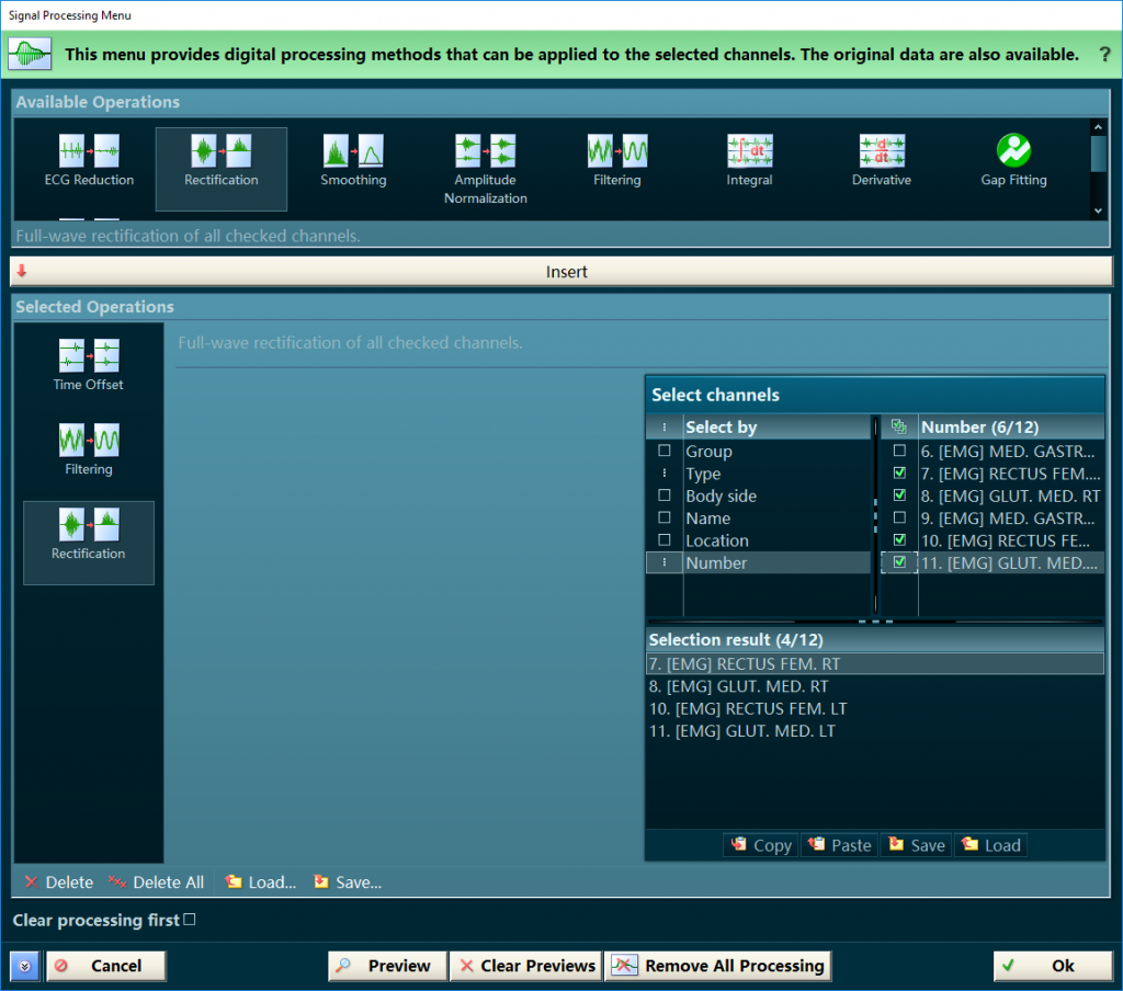
Order is important with respect to the signal processing operators, as the processes occur from top to bottom. If you intend to utilize an additional digital filter, make sure to place it above (before) rectification in the “Selected Operation” field. In the example below, the chosen signals are time-offset and filtered before being rectified:
You can add a 3rd party sensor or device via Analog Outputs through our Analog Input System.
Each system needs to be set-up for collection on their own RF channel. For example: If you have one Mini DTS system set-up to collect data on RF channel ‘A’, then you cannot set up another Mini DTS system to collect on this same channel. This will lead to data loss and unusable data.
To synchronize data, make sure all of your devices are connected to your MyoSync Master Station using a 3.5 mm stereo cable, and be sure to select the myoSync checkbox in the Hardware Setup in order to line up the data across systems.